Florian’s a busy man, I didn’t want to bother him if anybody already had the manual ![]()
If I don’t get any positive answer here by tomorrow, I’ll email Florian to ask him for an up-to-date version.
Thanks for the answer though!
1 Like

Regarding the hole and anti twist pin, do people feel any play when in high gear due to this fit?
I measured the protrusion on the hub to be about 5.78mm, and the provided drill at about 6.14mm.
0.3mm play at 21mm radius (42mm bearing diameter), would be equivalent to 1.39mm play at the pedals for 150mm cranks.
0.3mm / 21mm * 150mm / 1.54 gear ratio = 1.39mm
This seems significant, compared the the play in the gears.
On my M399 hub, I measure less than 1mm of play in high gear.
Regarding anti-twist pin play - I would have thought when the unicycle is fully assembled the bearing retainer friction would be enough so that no play from the “pin to hole gap” would be felt when wiggling the crank arm back and forth or from normal riding. With strong braking the pin might move a tiny bit in one direction, towards one side of the drilled hole, but when it bumped into that side it would stay there, and at the next braking event there would be no movement?
1 Like
The disc brake braking won’t affect it.
But, this now makes sense for me.
For me at least, pedal backward torque will be quite little. If friction is enough for that, then the pin will just wedge up against the hole in foward pedal torque direction and stay there.
4 Likes
Thanks so much!
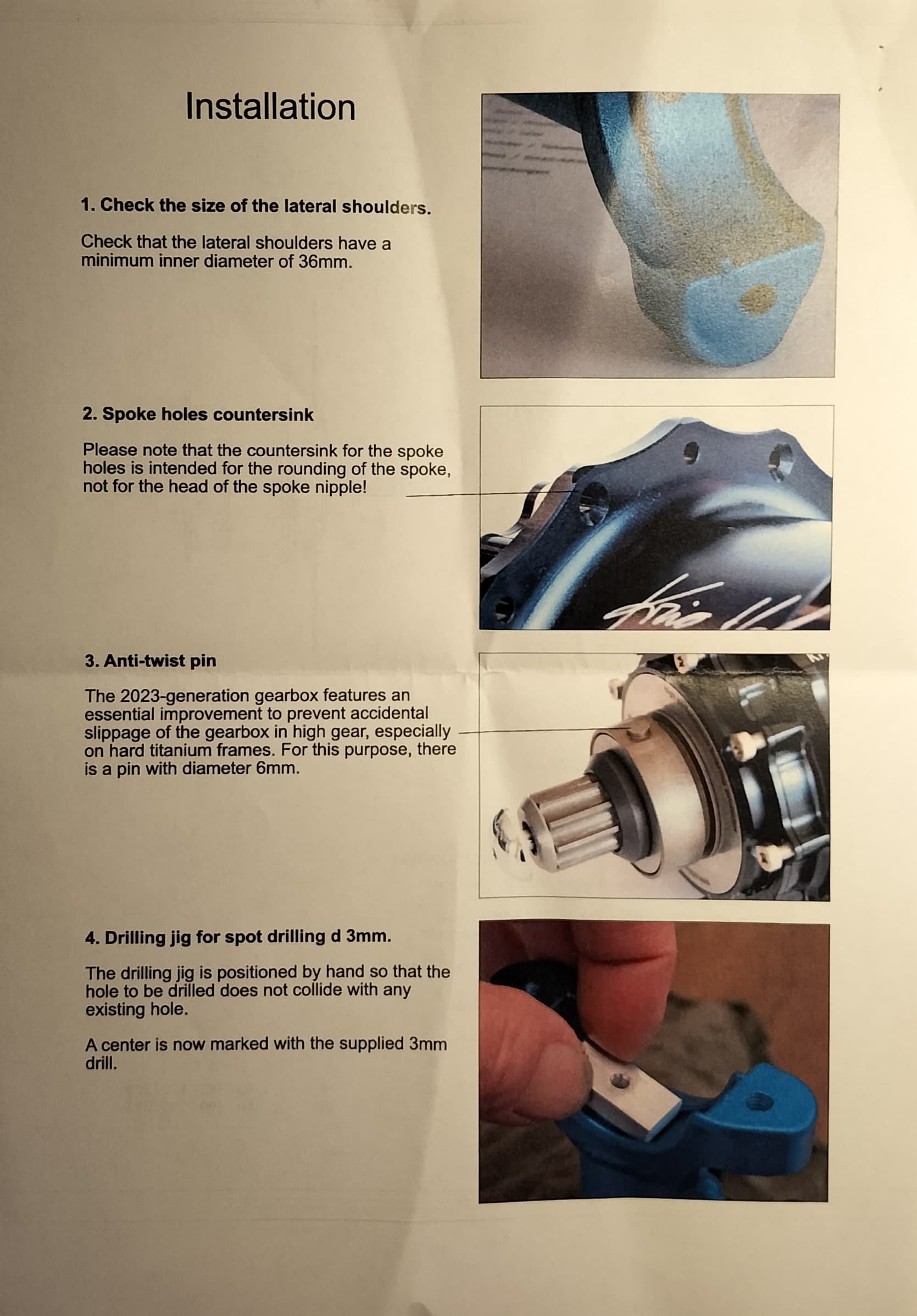
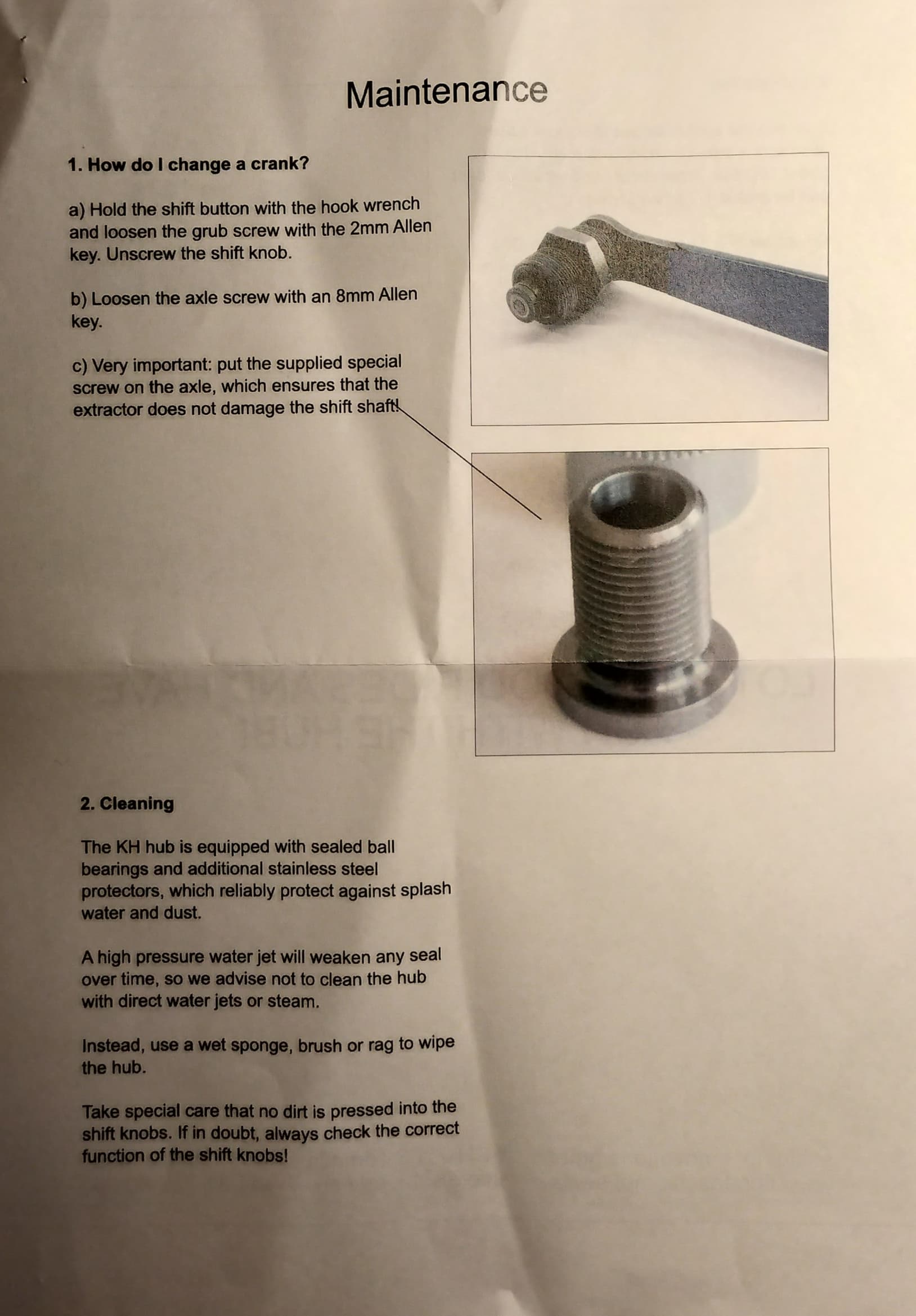
So, how do you all interpret the “2. Spoke hole countersunk” part?
Please note that the countersink for the spoke holes is intended for the rounding of the spoke, not for the head of the spoke nipple!
Why is there a reference to the spoke nipple?
To me it’s an obvious mistake. The intention must have been to reference the spoke head. I believe there are multiple issue with that sentence.
I guess rephrasing to something like this might be appropriate
“Please note that the countersink holes in the flanges are intended for the j-bend of the spoke and not for the spoke head”
3 Likes
Your message confirms what I think. Thanks!
FYI, if using a venture crank, you should probably use a crank spacer.
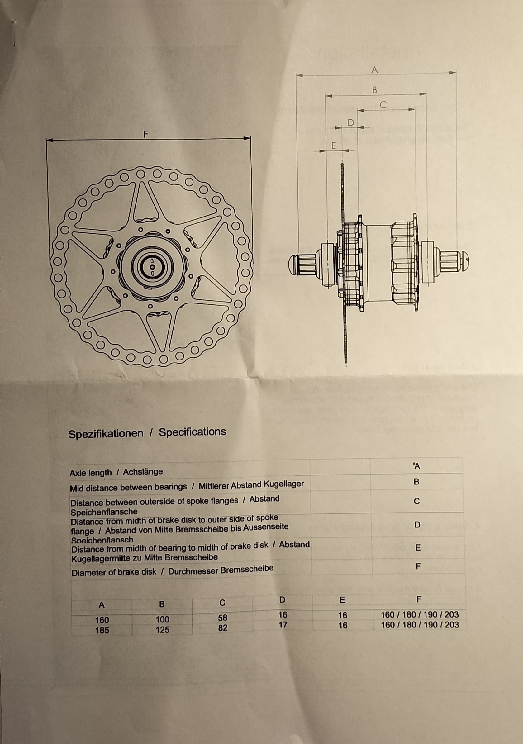
On the new schlumpf, I measured 17.4mm for this 16.0-16.5mm specification.
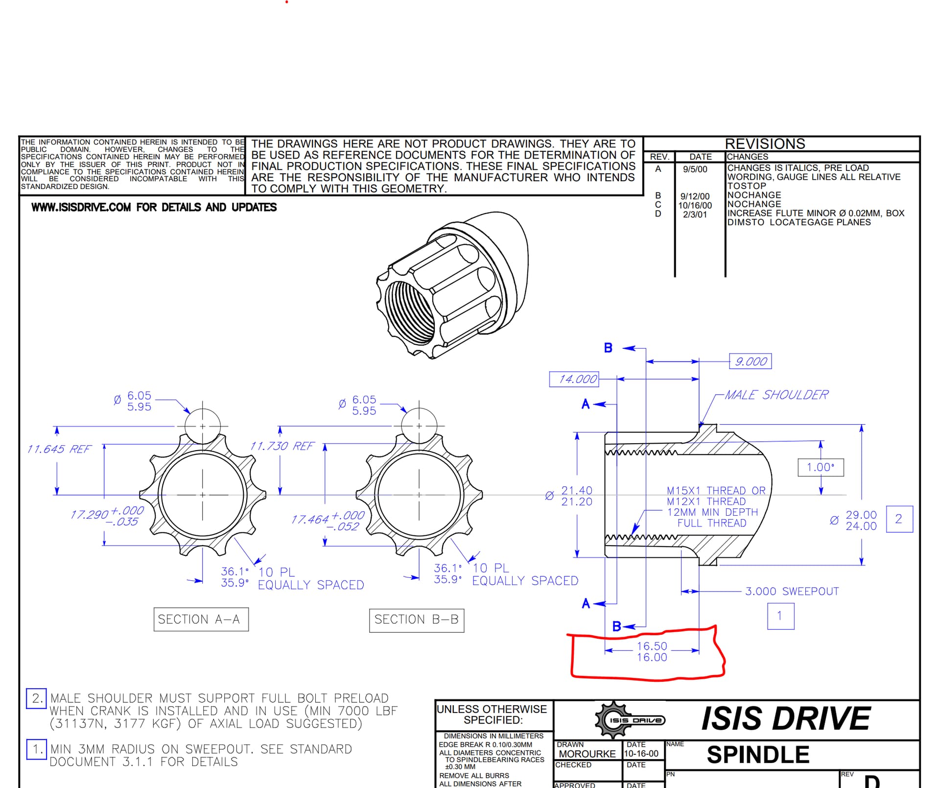
In addition, my pair of older Venture cranks also do not conform to the ISIS standard,
and measure 17.0mm for this 18.5mm+ specification
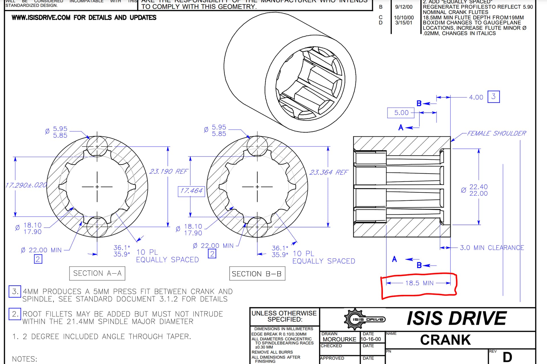
Therefore, IMO, a minimum of 0.4mm spacer is needed. Otherwise, the crank bolt will bottom out on the axle before the crank hits the crank stop.
A newer VCX crank I have measured 19.2mm, so that would not bottom out.
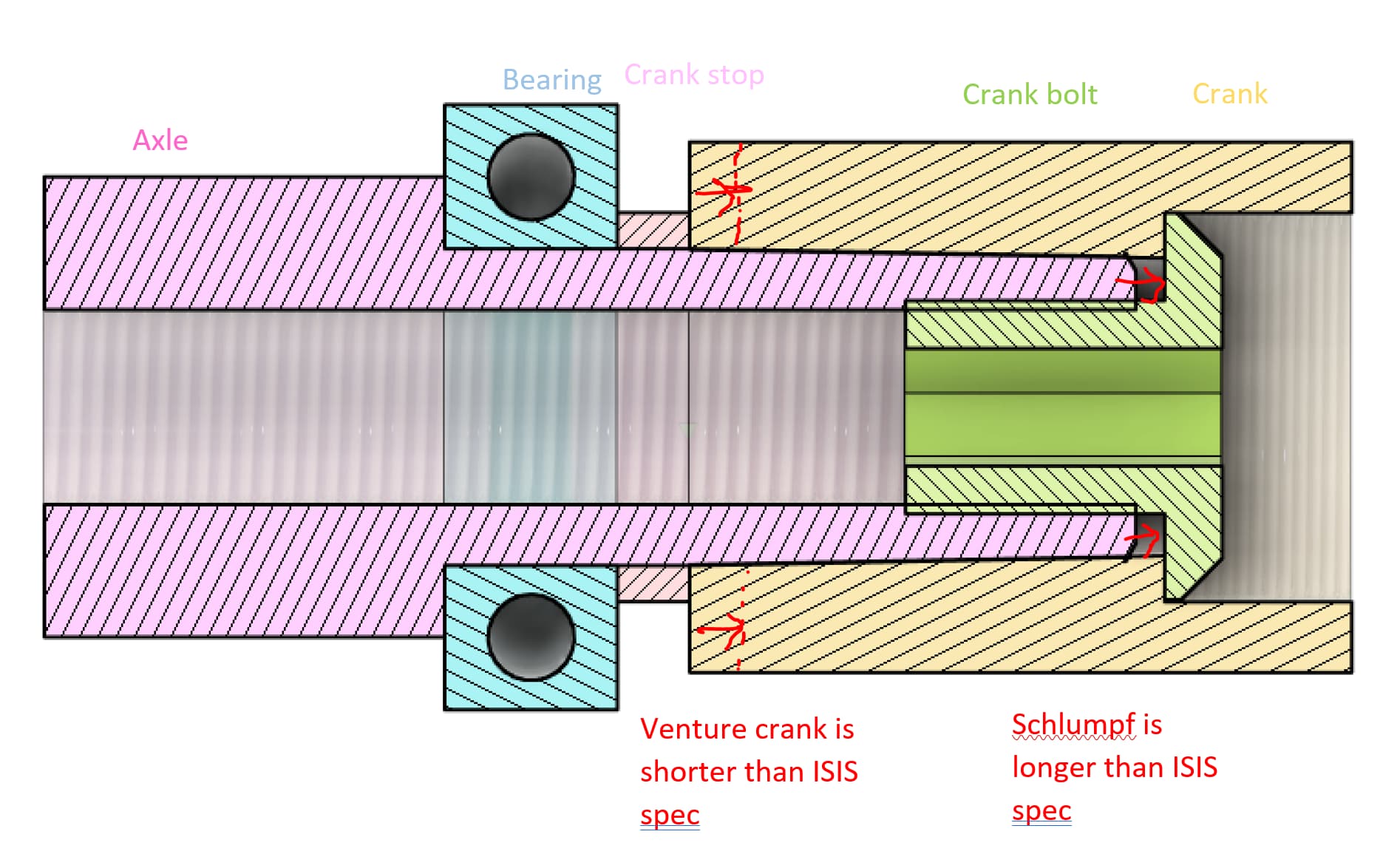
Simpler combined drawing of a “normal” interface:
4 Likes
Fascinating that you’ve noticed / noted that the new schlumpf is longer than ISIS spec. This would kind of explain why we’re seeing gaps and the discussion of spacers cropping up - whereas with the 2015/16 version there was no talk of spacers being needed and I’ve see photos of cranks going flush against the pressure rings.
I guess being longer than spec os better than being shorter!
I’m thinking of using a pair of KH Moment cranks on one of the new hubs - hope that’s are going to work without issue!
1 Like
I just installed mine, and it did not go 100% smoothly unfortunately ![]()
The shaft has to not only be clicked to the other side, but also pushed further for the bit to fully engage. The springs inside will want to push it out though.
My cranks are very far in, about 1mm from bottoming out on the end of the axle. (venture with 1.6mm spacers). If you have thicker cranks, and/or more crank spacers, then it will be less of an issue.
I have to push the 8mm allen wrench in with my left hand. While keeping inward force, apply torque with my right hand so that friction can then hold the allen wrench in place. Then I can let go of my left hand that is applying inwards force, and use it to hold the wheel in place. Then, I can applying more torque.
Left side, no problems at 40nm:
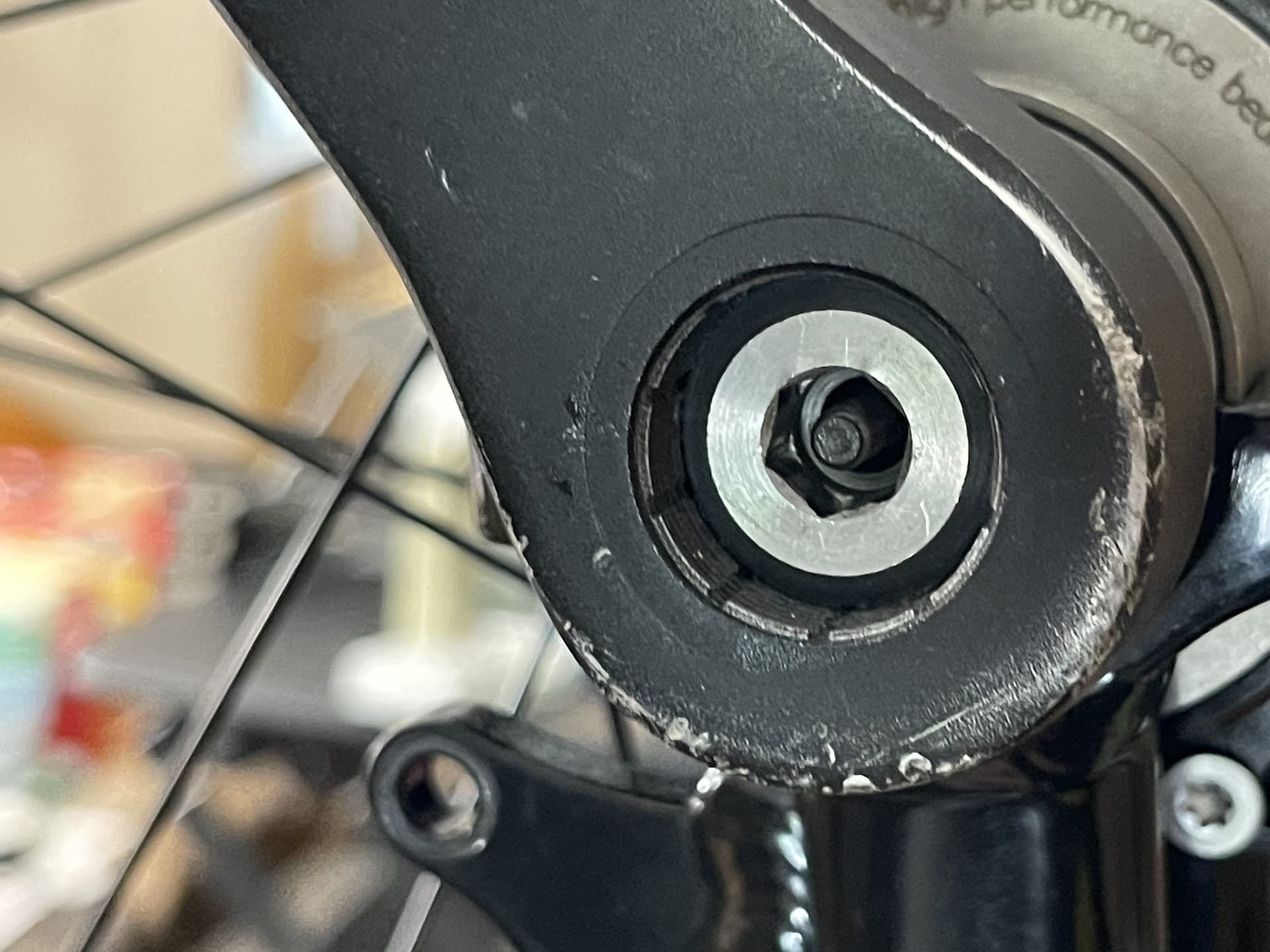
Right side, I messed up… I didn’t keep enough torque on the 8mm wrench when transitiong my left hand from inward pushing to holding the wheel, and the spring force of the shaft pushed my wrench out a bit, without me realizing.
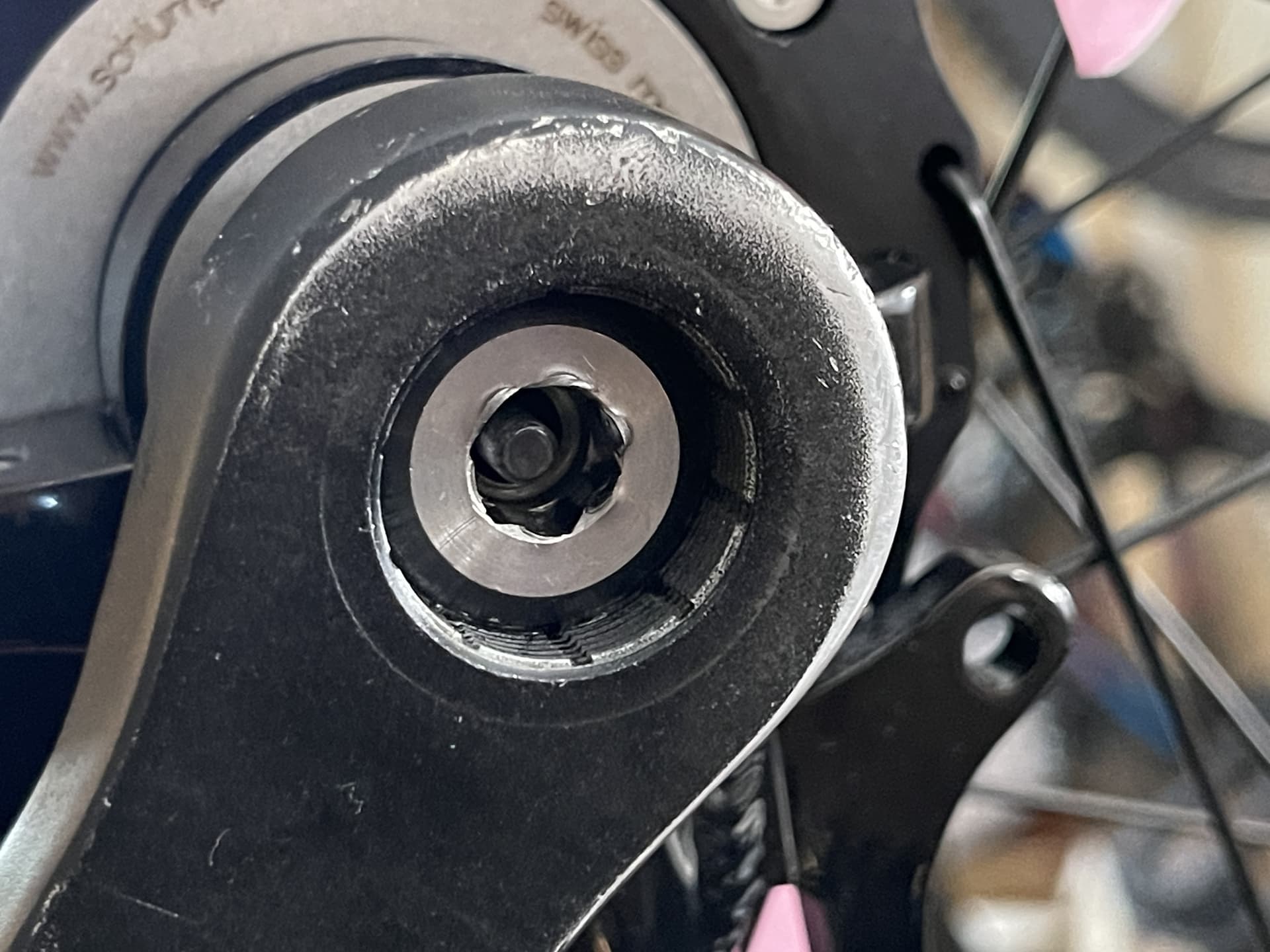
Both pictures have the shaft clicked to the opposite side. You can see it still overlaps with where the allen wrench should sit. It would stick out more if not.
3 Likes
Just thinking…. Could one drill a small hole or indented area to the 8mm hex bit provided. The hole would need to be big enough to allow the shifting rod space to not push up against it?
(All while ensuring that the wrench itself isn’t weakened)
Odd you highlight one side being worse to manage. I found the same thing - can’t remember which side, but I put it down to being more careful on the second crank. But now I’m not so sure and it was the same case for both G29er and G24.
Actually, I didn’t pay much attention to left vs right, so can’t say if it was actually more/less difficult on one side.
For me it was definitely lack of attention when I did the right side.
2 Likes
The more I think about this topic. The more I feel it is in effect something that is an area Florian is aware of - due to the fact he’s supplying the special bolt to put into the axle in order to be able to safely remove cranks. This bolt is there to give a surface for the crank remover to press on to. But it also seems like this is being used due to the fact the shifting rod is longer (it seems?!?) than previous models…
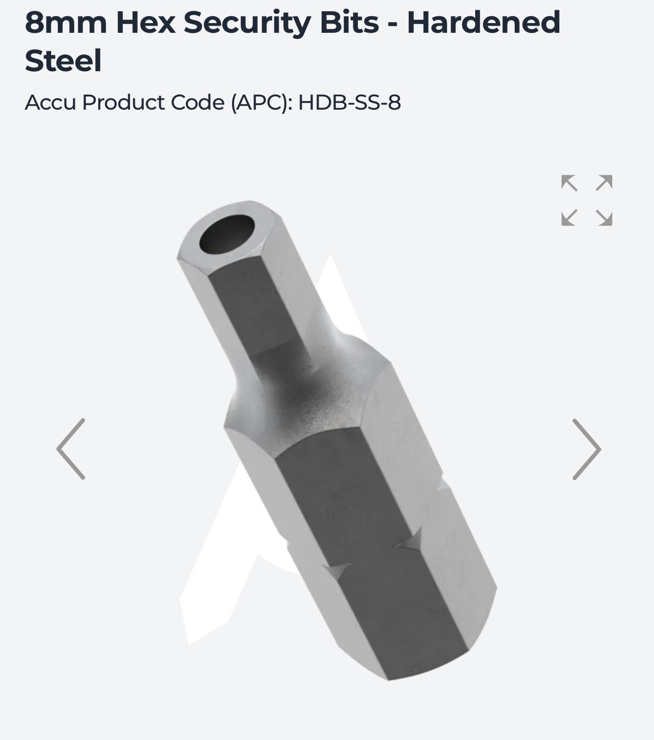
So if such a bolt is needed for removing cranks, then surely there is a need for a crank tightening bit that is also suitable for this.
I’m still thinking that perhaps a security hex bit like this - might, just might give us better fitment to the axle bolt, avoiding pressure from and to the shifting rod when tightening — and I just wonder if this would be enough to remove the resulting risks of rounding the bolts themselves.
Of course the better option would be a super solid axle bolt in the first place, or a pre-tightening bolt that is much tougher and with a bigger end section for the driver to be installed to. But still, as things stand finding workarounds isn’t a bad idea I feel ![]()
3 Likes
I messed up with one of my bolts exactly the same way, although mine is a 2015(M800+) version. It seems to be a problem common enough to be addressed.
1 Like
I’m toying with getting a pair of these M14s - as the new hubs don’t take standard bike M15 bolts - and see if I can drill out the centre section.
I am pretty convinced that having the washers on these kind of bolts helps with things being a smoother tightening process - as the official bolts seem like they could be getting gripped by the inner race of the cranks themselves which might make tightening harder — leading to the deformation
Standard unicycle bolts have washers for a reason, no?

1 Like
Doesn’t the design of the supplied bolts result in a less bulky head? It wouldn’t take much extra height for the bolt to begin to foul the gear change button, stopping it from fully going in. The pre-tightening bolt for the old models had a whacking great head, then once the cranks was seated with it using the correct torque the slimmer headed working bolts went on and could hold in the cranks without needing to be tightened so much. The thinness of the working bolt head and the resultant lack of depth for the hex key contact is the reason they round out so easily (been there - an oversized Torx bit saved my cranks and hub, but I haven’t tried to reuse that bolt)
1 Like
![]()
I think the above post from me was perhaps misunderstood. I wasn’t aiming to make a replacement axle bolt. But a pre-tightening bolt as per what you describe.
It seems obvious to me that these hubs should have been supplied with the pre-tightening one.
A shame, but if we can find a way to make one then that would be nice!
2 Likes
This seems like a good idea. You might have issues drilling out the center. I’d probably try to find a M14 nut to thread on the bolt to use to hold it in place in a vice while drilling out the center. Otherwise it would be difficult to hold it secure by clamping down on the round bolt head.
I might go ahead and order a set of these to try this as well. Are we sure the axle bolts for the hub are M14? I haven’t been able to measure mine since they are installed in the hub currently. Also what pitch are the threads?
1 Like
Not totally sure but tried a M15 and it was too big. Thread pitch again no idea. I’d just hope it would work.
Like your idea re drilling it.
Here’s hoping we can find a way to make this type of bolt!
1 Like