I might look for a place to heat treat my bolts before use…
1 Like
I think I kind of understand both points of view regarding crank spacers?
The first being not using spacers. If you consistently retighten up to the torque spec eventually the cranks will deform enough to bottom out against the pressure rings. In the interim, as long as you’re consistently checking and retorquing with a proper torque wrench, there isn’t much risk of the cranks loosening.
The second being using spacers. This one seems a bit more in line with the original ISIS specification. If you read through it it repeatedly references having the cranks bottom out on the “crank stop” (spacers in our case).
What are the consequences of using too much or too little pre-load?
If a crankarm has too much pre-load it will not bottom out against the crank stop on the spindle when initially installed. This will lead to the crank arm “walking” up the taper during some initial rides and a consequent loosening of the crank bolt. If the bolt is not constantly tightened until the crank finally contacts the stop, the result could be the crank falling off while riding or damage to the interface.
If the crankarm has too little pre-load it will bottom out on the crank stop prior to attaining a press-fit with the spindle. Depending on the magnitude of the press-fit, this may result in anything from a slight reduction in the load carrying capability of the interface to a “sloppy” fit between the crank and bottom bracket. This may also lead to creaking of the interface due to the slightly “sloppy” fit between crank and spindle.
I’m not a mechanical engineer though, so I can’t say which is more proper. My default opinion is to follow Florian’s guidance. Since the hub design is his, he’s in a better position to tell us what is correct / best practice for his design.
1 Like
I think my first option would be to go back to Florian to get a correctly heat treated bolt. Based on the photo and reports of the deformed bolts there clearly seems to be a problem with the bolts supplied.
Without knowing the exact steel type and recommended heat treating process, heat treating the supplied soft bolts would not be reliable.
2 Likes
I get you. I have my opinion but that doesn’t mean I don’t see the two schools of thought at work here.
Just wish it was more expressly delineated in the manual given the expensive nature of the beast ![]()
I’m a massive Florian fan - with the respect that goes with that, but that doesn’t mean I believe he’s infallible.
If we’d not somewhat critiqued things in a friendly way, the changes to the hub may not have been so forthcoming.
I’d second that as it feels like something that should best come from from the manufacturer - not least due to the item costing a fair whack ![]()
I’d love to see theses things ironed out just for the sense of making something near-perfect, but at the same time I can live with the rocky nature of the hardware as I find I do enjoy the process of being an early adopter ![]()
1 Like
I’m not sure what you’re talking about. Didn’t you get a pre-tightening bolt with your hub? I think I got one ![]()
1 Like
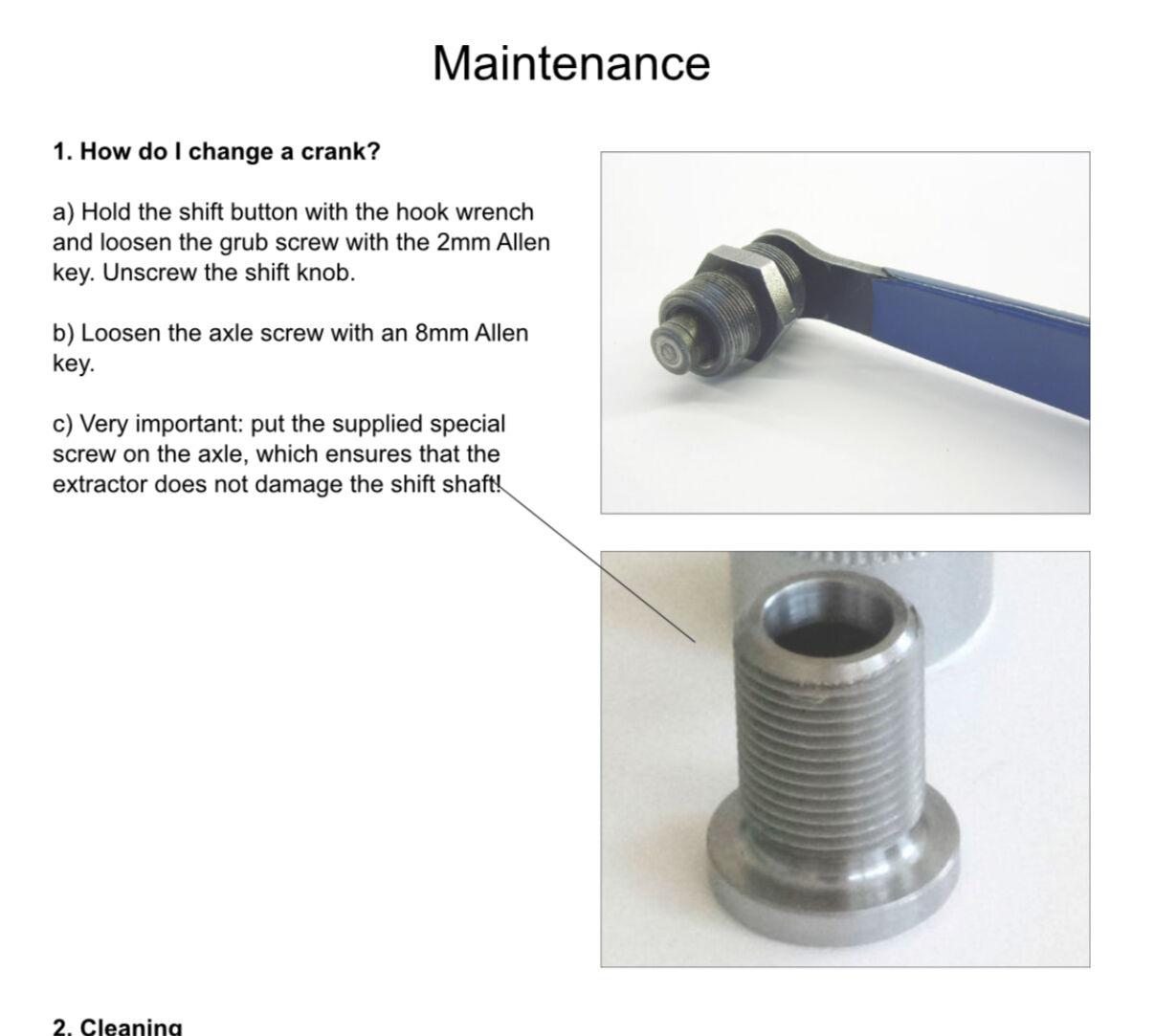
It looks like that but it’s not what you think it is. I belive it’s for protecting the gear rod when removing cranks.
1 Like
Yes this did confused me initially. But it doesn’t fit like an axle bolt, so it seemed like a spacer for allowing the crank remover to have something to press onto and avoid damaging the shifting rod.
Then the manual confirmed it:
Based on the spoke hole chamfer, does the wheel have to be built with the spoke closest to the valve going to the left side?
I think it is…but I’m not 100% sure.
Rims for sure often have a certain “handed-ness”. I think this might cause problems if the rim is the other handed-ness?
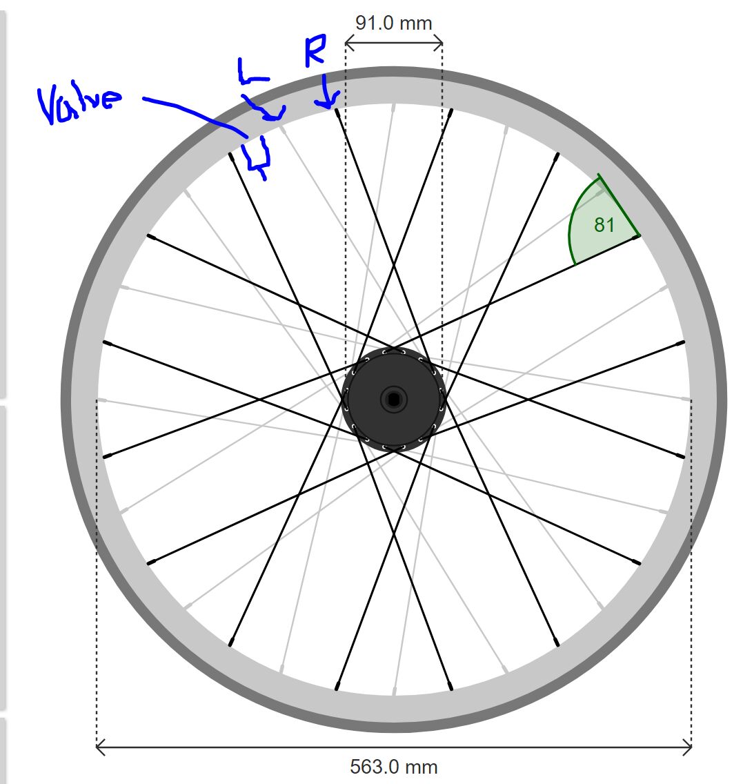
I’m not sure what potential issue you are looking for, but let me share a picture (seen from the right as in Sheldon Brown’s illustrations).
Light Bycycle EN933 36h. The “key spoke” is one hole away from the valve hole.
2 Likes
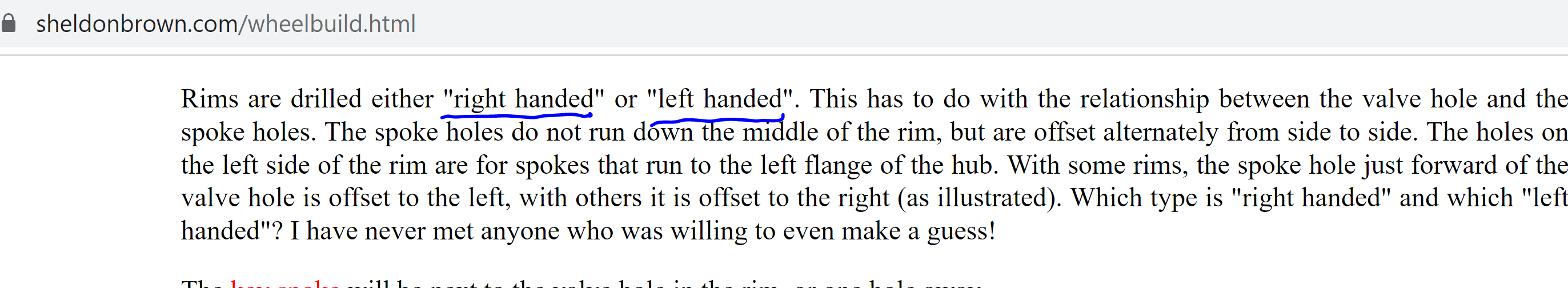
The Sheldon Brown wording about “handedness” is confusing.
Regarding the types of spoke holes, there are normally only two types - holes which are slightly displaced to the right-hand side of the rim (as viewed from above, as if riding and looking at the top of the rim) and holes which are slightly displaced to the left side.
So the two possible patterns are:
- L------R------L–O–R------L---- etc. (where O is the valve)
- R------L------R–O–L------R---- etc.
Usually, wider rims have greater L and R displacements.
Rarely there are no displacement (i.e. all holes are in a line, the center line unless rim is asymmetric).
In theory the holes (or their sleeves) could be angled forwards or backwards as well, but that would not work across varieties of lacing patterns.
The Sheldon Brown description is from the right-hand side and assumes type 1 “handedness”, so it is a bit confusing to follow if your rim is type 2.
It is easier to explain what the lacing should look like when it is done than explain how to do it.
So here is a list to check when the rim is initially or nearly laced up (before truing):
- the 2 spokes nearest the valve hole MUST angle to the hub in OPPOSITE directions, away from each other (for pump access).
- all spokes from the right-hand flange SHOULD connect to a rim hole on the right-hand side as viewed from above (and similarly left flange to left displaced rim hole as well).
- when forward pedal force is applied, the tension is on the so-called “trailing” spokes, and these SHOULD all be connected to the hub flange with the spoke head out, so the “shoulder” of the J extends along the inner side of that flange.
- of course there should be an obvious symmetrical pattern.
And of course, shorter spokes on the disc rotor side.
And probably the spoke heads should NOT go in the “dent” (as discussed elsewhere).
You will probably find that the spokes with head out on the non-disc side (narrower flange on Schlumpf hub) have some sideways movement (before full tightening), and these spokes (a quarter of the spoke count) good do with a brass washer under the spoke head.
[EDIT: and of course, as some wise people have said: “rules are for fools - experts make 'em, and experts break 'em” and “there is an exception to every rule” ![]() ]
]
2 Likes
I’d switch “must” and “should” in these two statements… ![]()
I’ve gotten this wrong before and on most wheels, it’s not the end of the world. Doesn’t look great, but with 36 spokes on anything 24" or bigger, you probably can still get most pumps in. I’d still correct it if I got it wrong because it could be annoying, but in a hurry you can get away with this wrong.
If you don’t do this, you’ll have some funky spoke angles on most rims.
2 Likes
I know for lightbicycle rims, they are drilled with angles to the left/right.
@Hammer has a type 2.
4 of my 5 lightbicycle rims are also laced type 2 (WR38 and AM740). My older RM29C06 is laced type 1, but it is possible I did it wrong in the past.
I was lacing a brauss rim, which I think is neither type 1 nor 2. I tried it with type 1 pattern (key spoke next to valve) and I couldn’t get it to work…
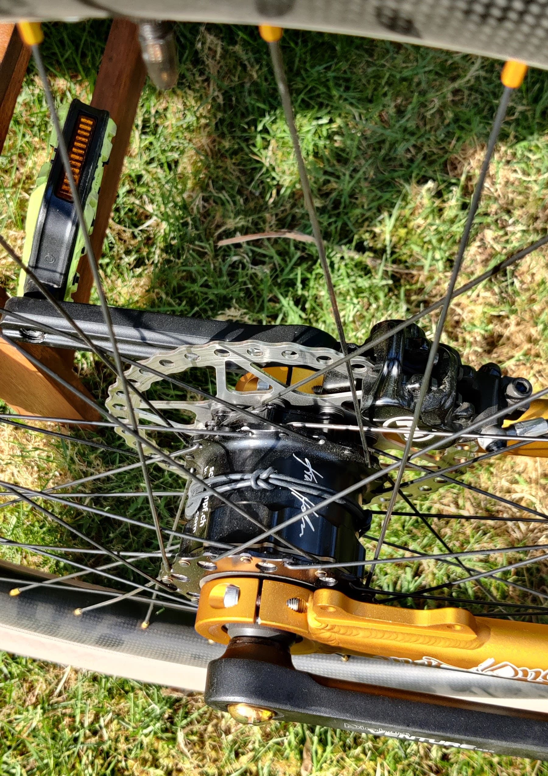
The schlumpf chamfer forces the left-hand spoke with head out, to be counterclockwise from the right hand view, from the nearest right-side spoke that is head out.
This means the key spoke has to be one hole away if we want to keep point #1
So I unlaced and switched to using type 2 pattern.
2 Likes
Does anyone have the new hub manual as a digital document (pdf)?
1 Like
I suspect the core collaborators / frame makers may, but the fact is this is likely private Intellectual Property of Schlumpf Innovations.
I did ask for a CAD file for the rotor due to the project with BrakeStuff - but never heard back and I don’t really blame Florian on this as it would be a favour to me, given that no engineer is going to really enjoy others digging into the details of their design.
In other words I doubt it as the hub isn’t open source
(I’d love the file to add to my collection, but I’m not holding by breath)
I meant the user manual we got as a physical copy with the hub ![]()
1 Like
Ah so sorry. I definitely read that wrong ![]() I don’t really know what version you got shipped with the new hubs.
I don’t really know what version you got shipped with the new hubs.
Did you get the group email from Florian with the first ever version of the manual? (The one with areas / topics, missing)
I don’t remember so ![]()
Montageanleitung.dt.engl.2023.3.engl.red.pdf (2.0 MB)
Let us know if this differs to the printed version. I should say that this is with the out of date specs and details so should be read with a handful of salt ![]()
Hope it helps!
1 Like
Thanks!
I was looking for info regarding the countersunk. I have let the manual to my wheel builder so I don’t have the copy any more. And… The first version doesn’t seem to include any info ![]()
Have we had news from Florian on that point?
1 Like
Should be an easy thing for Florian to email out to everyone. Have you emailed him?
Alternatively perhaps someone here with the new version of the paper manual still in their possession could digitise it for you/others in need of a PDF version.
I wouldn’t mind seeing an up to date version!
1 Like