Schlumpf 2022 Build Questions

The dishing offset from the hub (assuming rim has center line spoke holes) is:
( (D+E)-(B-C)/2
For the OLD? diagram, this gives 8mm.
For the NEW (as at 10May) diagram this gives 11mm.
My 125mm hub that just arrived conforms to the new diagram btw, so I guess the 100mm will too.
The new diagram is now on Florian’s unicycle hub webpage.

Regarding the 6mm frame drilling to hold the disc side bearing, it is a bit scary.
On my Nimbus frame there was already a small hole, so the pilot drill and jig could not be used.
The main possible issue is if the existing hole was not centered left to right in the bearing holder.

I think another issue some people may have is the rotor spacing and the rotor fixing screws.
I got received 3 spacers in the package, each with 3 holes (partially countersunk), that can go on the hub side of the rotor as a layer to move the rotor 1mm outwards. On my frame and caliper, it seemed like I needed the 1mm spacing to properly center the rotor in the caliper without extreme adjustment of the caliper.

However it seemed to me that the 9 provided M4x16 countersunk Torx screws were still a tiny bit too long as they seemed to be “bottoming out” rather than tightening. You would need the longer screws for multiple spacer layers, but for no spacer or one spacer layer, maybe M4x12 would be better.
I’m reasonably sure about the “bottoming out” but maybe I am either unlucky or over-cautious, so I am interested in the experience of others.

You can also source 14mm screws but it seems to be a more unusual length.

As I remember 16mm was bottoming out for me with three spacers on my 100mm hub. However my spacers is probably also slightly less than 1mm each. And I have the initial version of the hub (I’m not exactly sure what was changed in the “later” version)

1 Like

I’m not sure how you found this mathematical expression. Could you explain it to me like I was five? :smiley:
Thanks for the numbers, though :slight_smile:
I now get the following values:

They are pretty similar to the last ones, so I guess I’ll be good anyway :slight_smile:

It is said that:

The drilling jig is positioned by hand so that the hole to be drilled does not collide with any existing hole.

So I guess you can drill the hole anywhere in the bearing holders and it’ll be OK.

That seems to be the intent from the manual picture, yes:

I am guessing but I suspect they went this route due to some frames having their manufacturing hole off centred.

But I personally would check if there is a hole already there in the right place and if it is hopefully smaller than 6mm.

If it were to be centred and smaller I think I’d look to widened it with the 6mm drill bit.

I have feeling the guidance in the manual is being extra careful not to weaken the bearing mounting area. Which could well be a wise thing to do - but with my Flansberrium frame the hole was drilled right the way through the area so I can’t (personally) see why one couldn’t just widen an already existing, centred hole :hole:

I think I need to drill this hole at some point on a KH frame… and I will probably try and make a video as a how-to. Oddly enough I see the new KH frames have a hole in their caps:

So that would imply we are to secure the retaining bolt in that section.

As it does contradict the manual I would prefer to drill the fork section. For this I would use the little alignment template, secure it on the mount with some clear tape (tight!).

Put fork leg in a vice and get it perpendicular to where you’re aiming to drill. And then set the drill to very low torque or speed. Even if I had one use a hand drill.

Drill the pilot hole only down a smidge. Just enough to locate the tip of 6mm bit and stop it from slipping.

Remove the alignment jig - and then very very slowly drill down straight with the 6mm and keep taking it away to check how deep it’s been going. You can use a small piece of cardboard to check the depth and measure it against the hub’s securement nub/pin.

Fear not @Maxence you clearly have options if you were to get it slightly wrong - but I doubt you will if you go very slow with the 6mm drill bit.

:muscle:

2 Likes

OK regarding the formula for the “dishing offset”…

We start by noting that a unicycle frame is a pretty simple symmetrical thing generally, and the wheel is supported by two bearings of equal size on the frame legs. So the wheel should spin in the center of the frame so that the rubber hits the road exactly between the two bearings, which will spread the load equally.

Sadly the wheel hub is not symmetrical because of the need to allow space for the disc brake rotor. In fact the two flanges that allow the spokes are NOT positioned symmetrically, ie centered (which they would be if there was no brake) but are shifted (or offset) a small distance away from the brake side. This is the “dishing offset”.

So the center of the flanges IDEALLY would be the same as the center of the bearings, but they are not, so we need to measure (or calculate) how far the centers are displaced (ie offset).

So let us measure these two centers in mm from the midpoint of the brake side bearing:

The bearing center is 50mm away, i.e. half the bearing distance, B of 100mm.
So bearing center is 50 or B/2.

The flange center is midway between the two flanges.
So the left flange is 32mm away from the left bearing, that is (D+E) or 16+16.
And center of the flanges is another 29mm along (29 is half the flange distance, i.e. C/2).
So adding these we get that the flange center is 32mm+29mm from the left bearing.
So flange center is 61 or D+E+C/2.

The dishing offset is the difference between flange center and bearing center.
That is 61mm - 50mm = 11mm.

Or (D+E+C/2) - (B/2) = 11
another way to write it is (D+E) - (B-C)/2 = 11

This means the disc side spokes are shorter and more in the vertical plane.
And that means the disc side spokes have less leverage to balance the sideways forces that the other side spokes exert on the rim, to keep it in place, which means that the lengthwise tension on those disc side spokes has to be more than on the other side.

I tried this explanation on a 5 year old but they got bored and left the room :wink:

2 Likes

Thanks for this clear explanation! I speak English like a 5 year old and I didn’t got bored :grin:
I naively thought the dishing offset was the distance from the disc location to the left flange - as the disc is approximately where the flange would have been if there was no disc. I now understand what’s this offset is. Thanks so much!

This is all really interesting.

I have long wondered how UDC’s spoke calculator does things like this.

And for the new 100mm Schlumpf hub it uses:

Disc side - Flange Width A: 34.4
Non-disc side - Flange Width A: 76.8

When you add these together you get: 111.2

Which seems like 100mm hub + 11mm offset.

I could be wrong as my maths understanding is like a 4.5 year old child :grin:

The UDC calculator has a slight difference in that it uses a different value of C (flange width) in its calculations. It measures flange width (probably more appropriately) from the center of the left flange to the center of the right flange. (where C is measured from the outside of the left flange to the outside of the right flange). So (in the simple symmetrical case), the UDC width will be C less half the left flange width less half the right flange width (i.e. a couple of mm less than C).

Remember that there are actually 4 types of spokes in a standard wheel lacing:

  1. disc side spoke with head on the inside of the left flange;
  2. disc side spoke with head on the outside of the left flange;
  3. non-disc side spoke with head on the inside of the right flange;
  4. non-disc side spoke with head on the outside of the right flange.

1 and 2 are almost the same (2 is a tiny bit shorter).
3 and 4 are almost the same (4 is a tiny bit shorter).

But note that this assumes the rim spoke holes are central (not an asymmetric rim), and also assumes the rim spoke holes are not staggered. Usually they are very slightly staggered (holes alternate from SLIGHTLY left of center to SLIGHTLY right of center, but it is usually barely perceptible to the eye.

The UDC method give two lengths: the average of 1 and 2, and the average of 3 and 4 (roughly).

The strange values (34.4 and 76.8) are affected a bit by the different measurement discussed above (due to flange thickness), but we have to dig deeper to understand where they come from:

I assume that at the heart of the UDC calculator there is a calculation module which assumes the hub is symmetric. I guess the two “fake” hub flange widths (34.4 and 76.8) are used for two calls to the “calculator heart” to trick it to give the right results for an asymmetric hub.

It looks like UDC uses 55.6mm for the measured flange width instead of 58 (due to measuring from the center instead of outside) and the flange center would actually move slightly to the right due to the left flange being thicker, making the computed dishing offset (say) 10.6 instead of 11?

(I assume UDC has updated to the recent dimension changes!)

Now the distance from the left or right flange to the bearing center point would be half of 55.6 if the hub was symmetric, i.e. 27.8mm (and one call to the internal calculator would be good for the spoke lengths from either side, as they would be equal).

But the asymmetric hub has a distance from the left flange to the bearing center point of 27.8 - 10.6 = 17.2 and doubling this to get the equivalent symmetrical flange width gives 34.4.

And the asymmetric hub has a distance from the right flange to the bearing center point of 27.8 + 10.6 = 38.4 and doubling this to get the equivalent symmetrical flange width gives 76.8.

So two calculations using the simple symmetric formula but with a hub width adjusted as above by those two offsets (34.4 and 76.8) will give the two spoke lengths that are needed.

I tried to test this explanation on some kids, but they all knew it would be boring and ran off and hid in their bedrooms and pulled the blanket over their heads :wink:

2 Likes

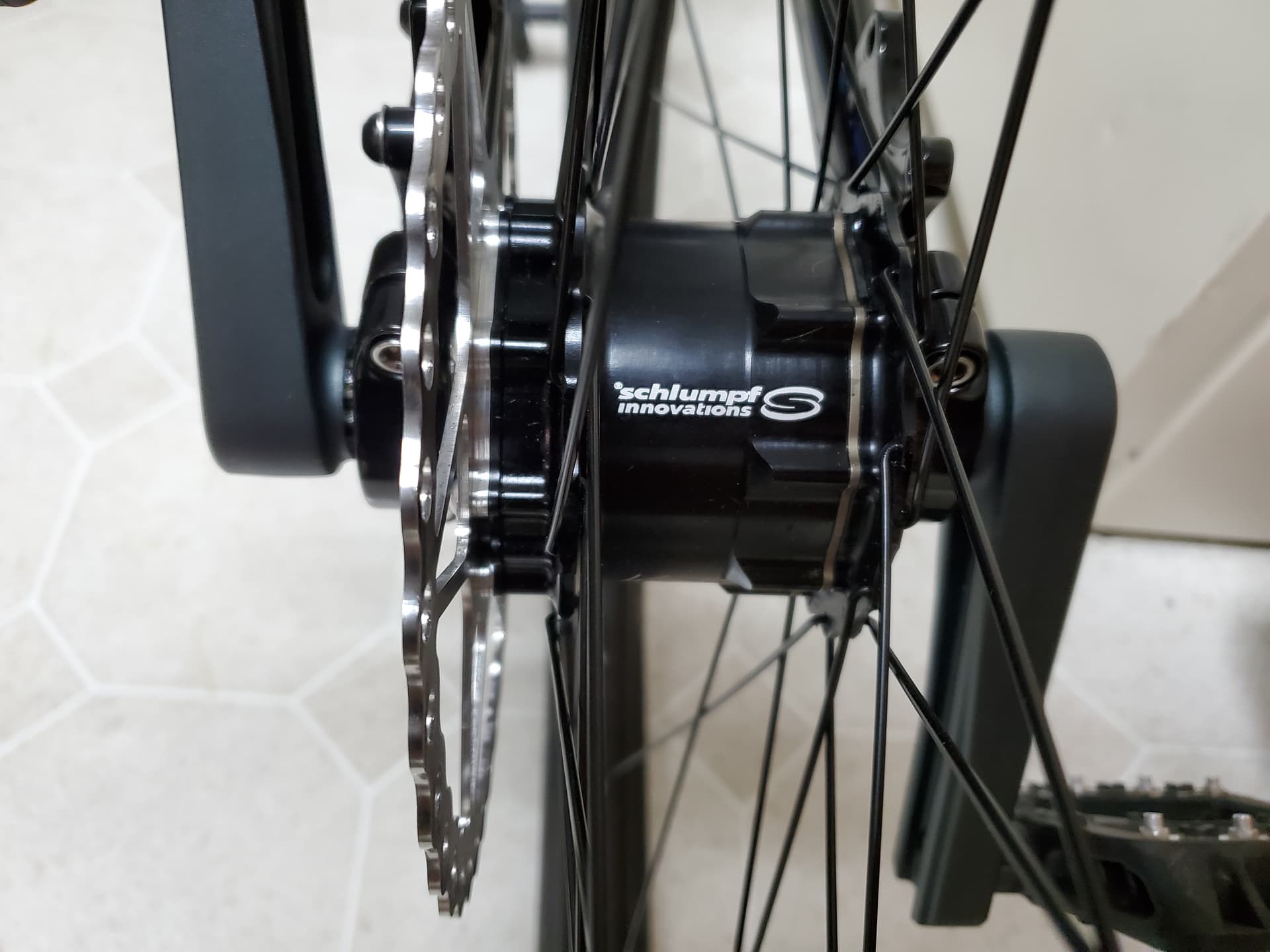
I thought I should share details of my initial Schlumpf hub experiences:

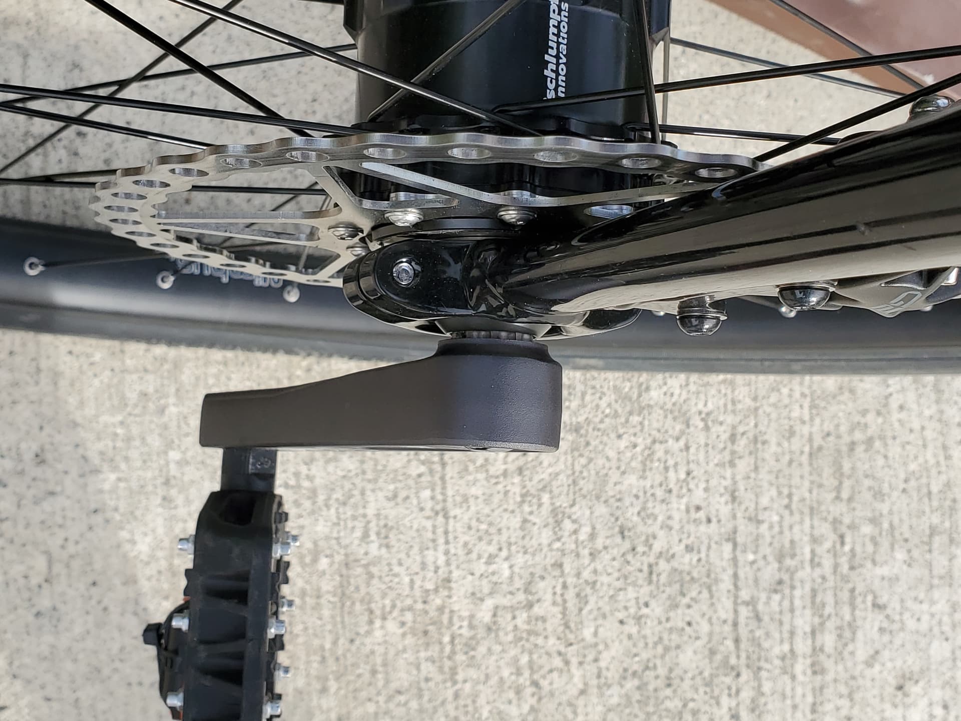
It is a 125mm 36H hub, with 203mm disc rotor.
I switched my order to 125 from 100, with the larger rotor, after reading posts above about clearance issues.
The hub is the latest minor variant (slightly different dimensions, longer countersunk rotor bolts and 1mm spacer provided in the package).

I had asked for ‘Eternity’ to be the optional hub engraving and, interestingly, there is a clock produced by Florian with that same name (which measures time in centuries), and so my package included a brochure about that artistic clock!

On first handling the hub it seemed that there was a bit of roughness in the gearing and/or bearings which could be felt when turning by hand an evidenced at about once per revolution on average. I put in a whole extra ampoule of oil and am hoping the hub will “wear in” and become smoother after a while. I’m not too worried about it now - it is less noticeable when the hub is mounted on the frame and spun by one crank.

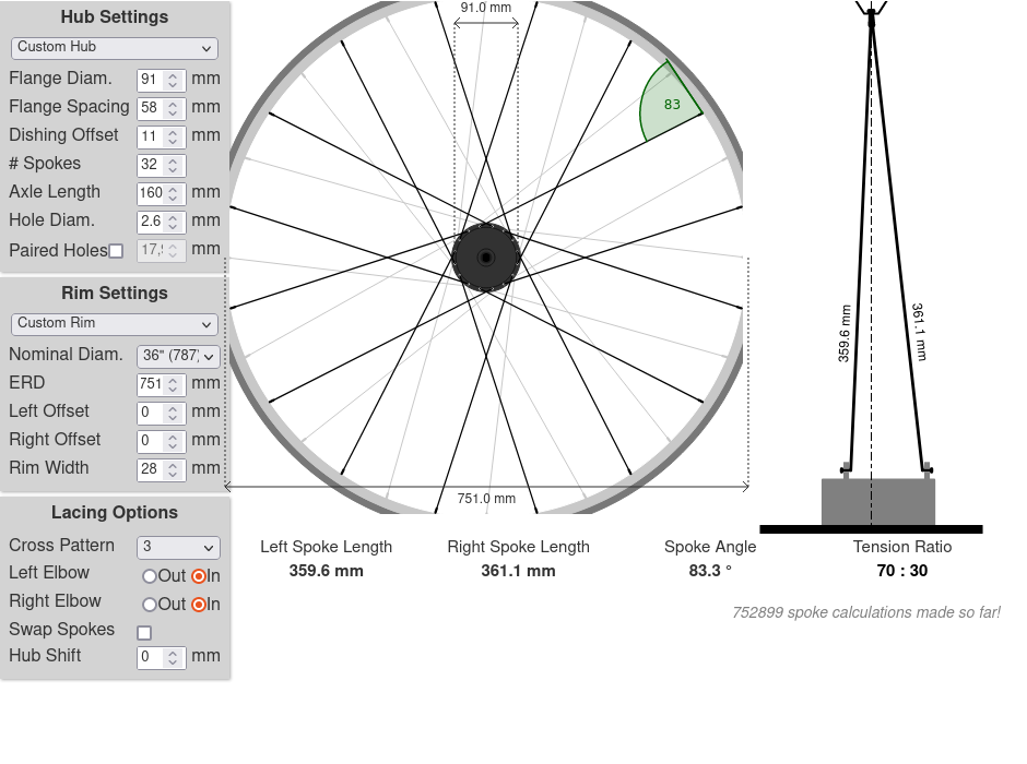
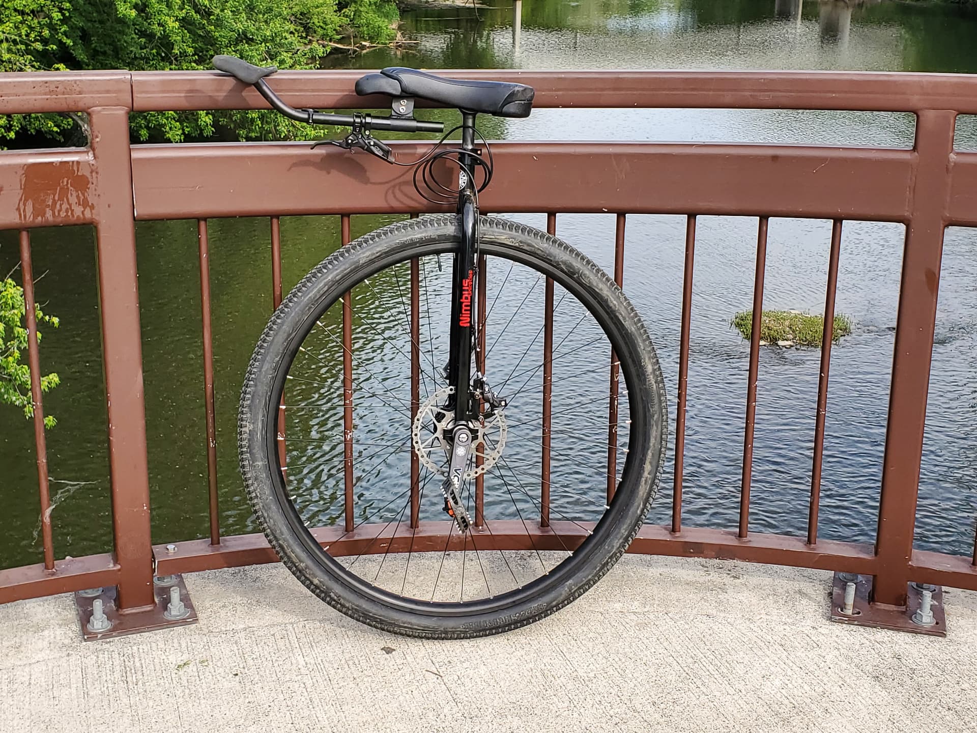
My build plan is to put the hub on an existing 125mm frame which originally came from a nimbus 32, but lace the hub to a 26in dominator-2 wheel from another existing unicycle in my “stable”.

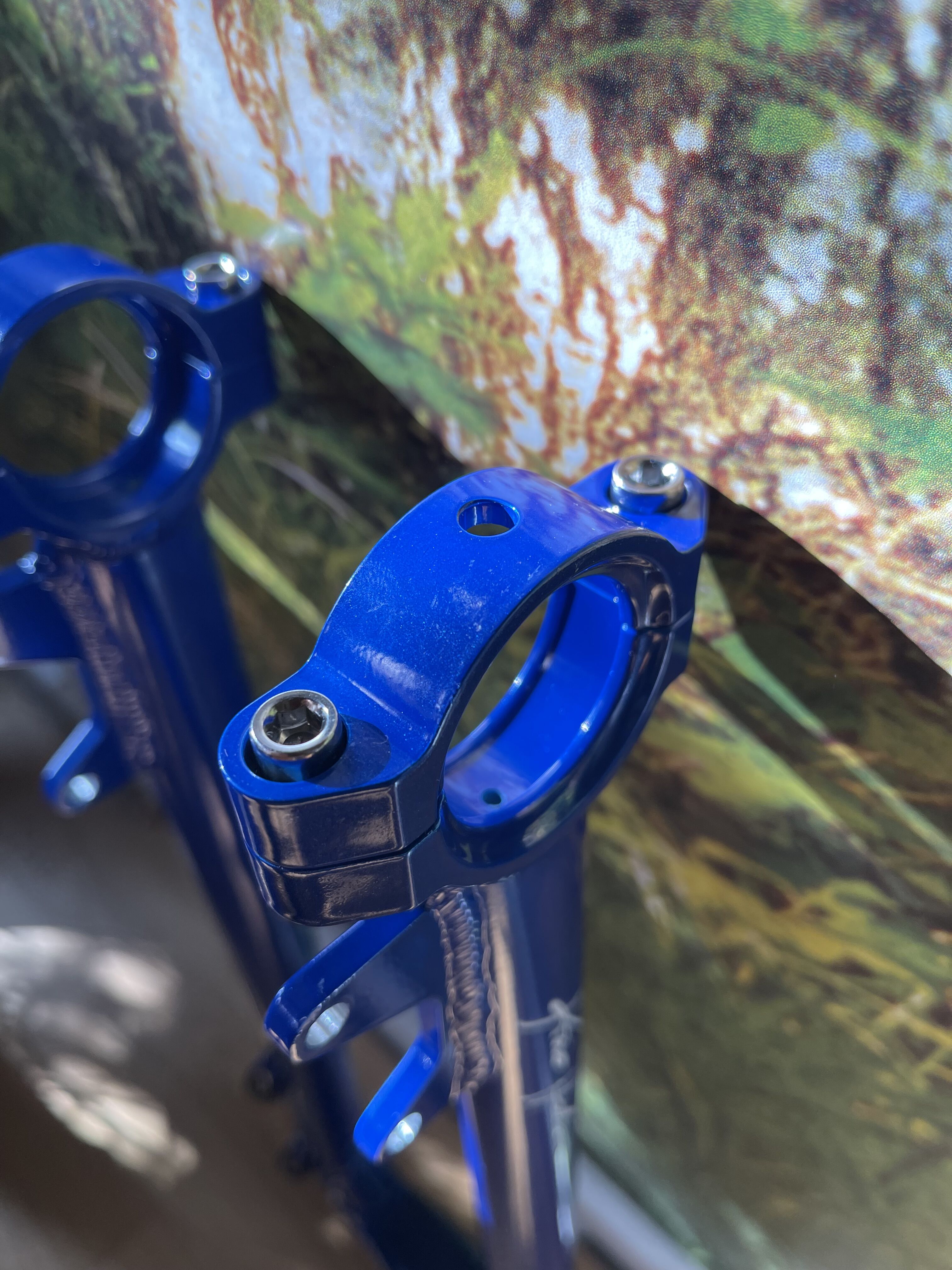
I re-used the existing small hole in the frame bearing holder and enlarged it to 6mm for the retaining nub on the hub bearing - that was a bit tricky but luckily the existing hole was pretty much central.

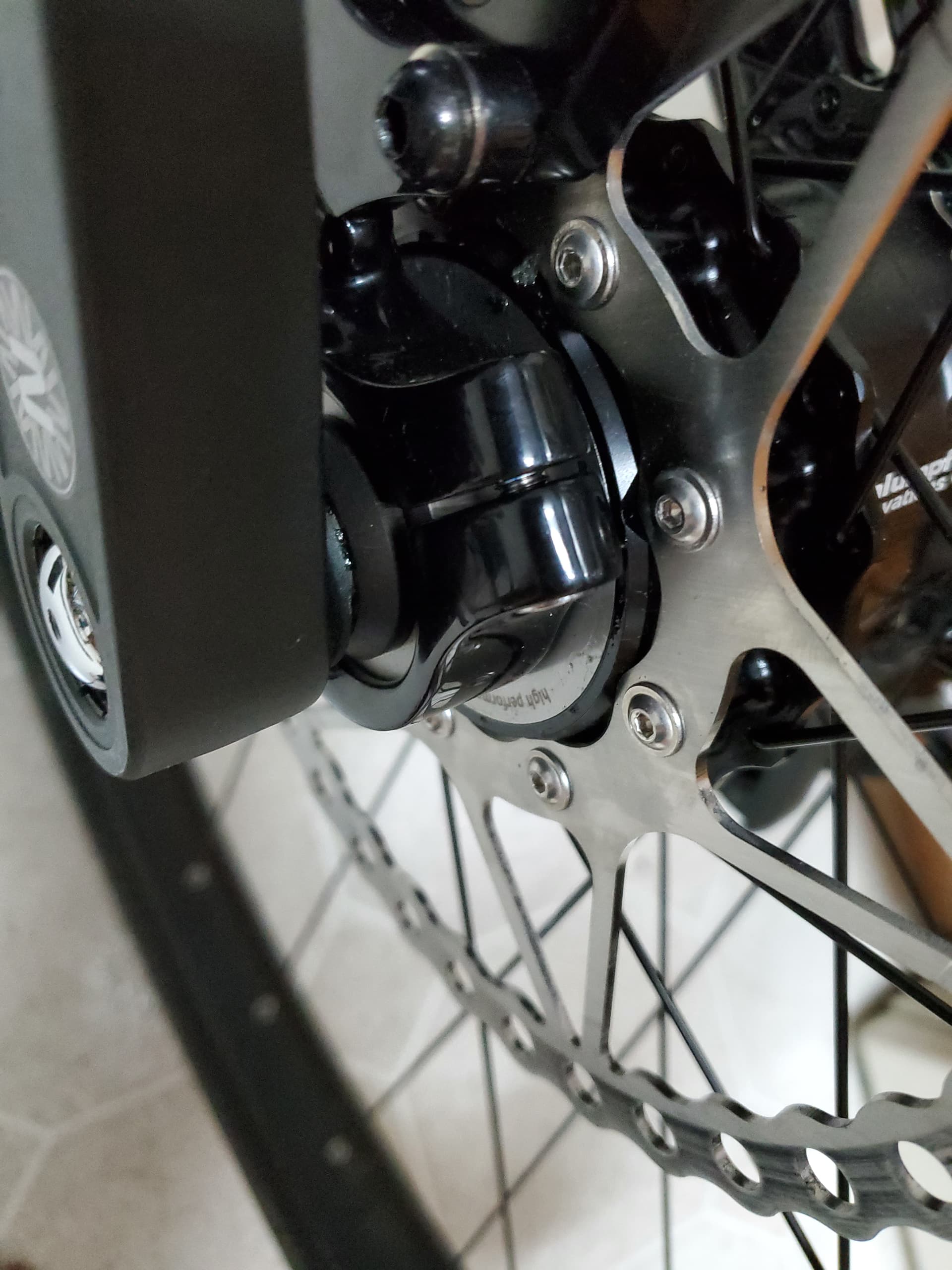
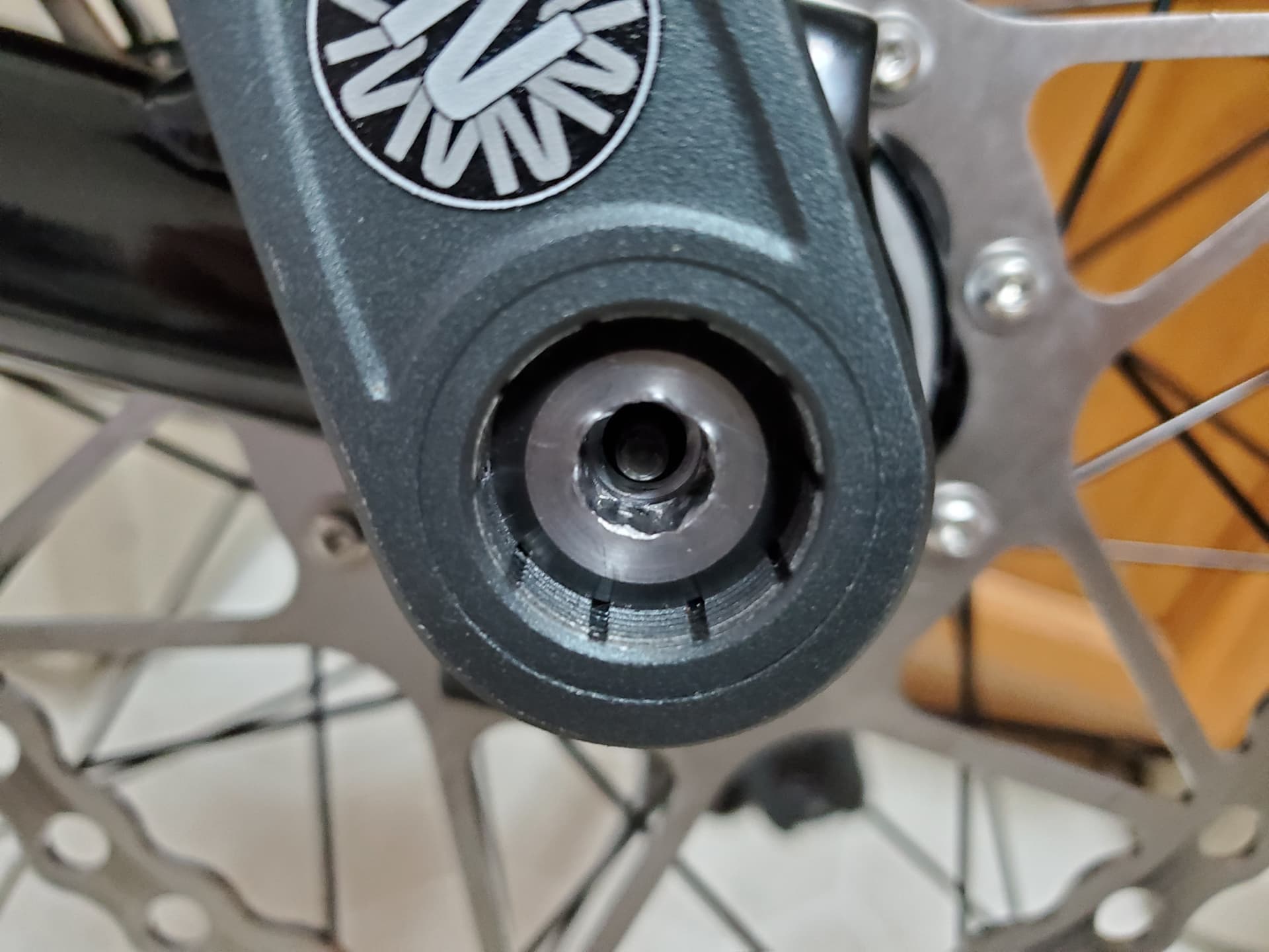
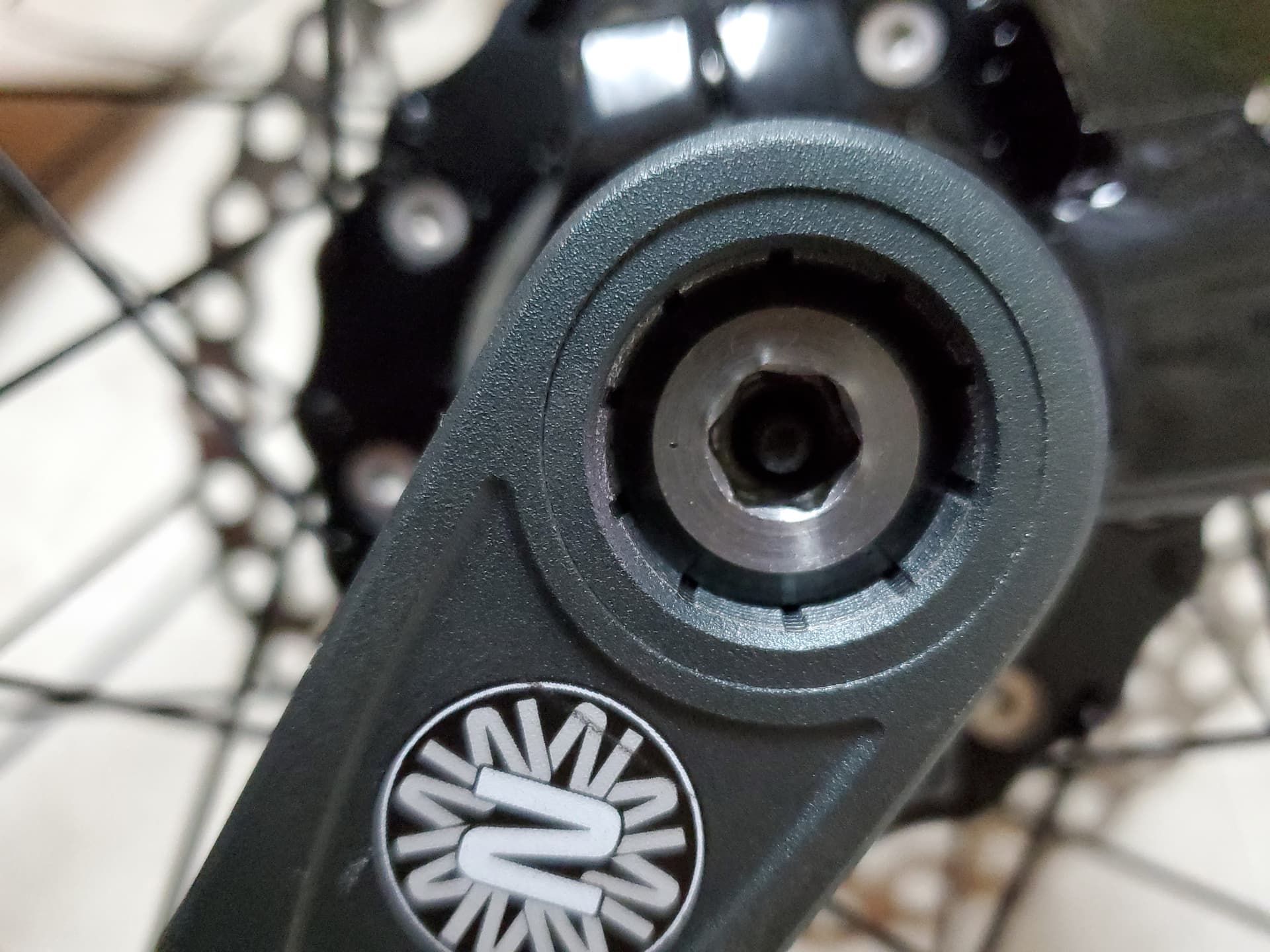
Putting the rotor on (temporarily, as it will have to come off again for spoke lacing) I noticed that the 16mm Torx screws (new, longer) seemed to “bottom out” so I temporarily replaced them with 12mm hex socket head screws until I can find some 12mm or 14mm countersunk Torx screws (not easy to find!).

[EDIT: wow, I just got some shorter Torx screws in the mail from Schlumpf Innovations without even asking!]

It was tricky to align the rotor with the existing caliper (using a new adaptor for 203 rotor) in this first test fitting - it seemed to need the 1mm spacer, but I’m pretty sure it won’t be a problem in the build - maybe just a bit of fiddling and filing.

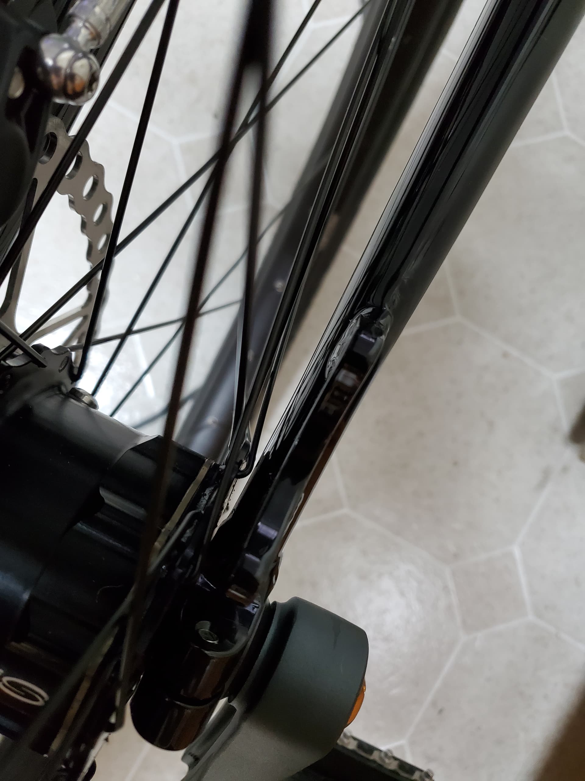
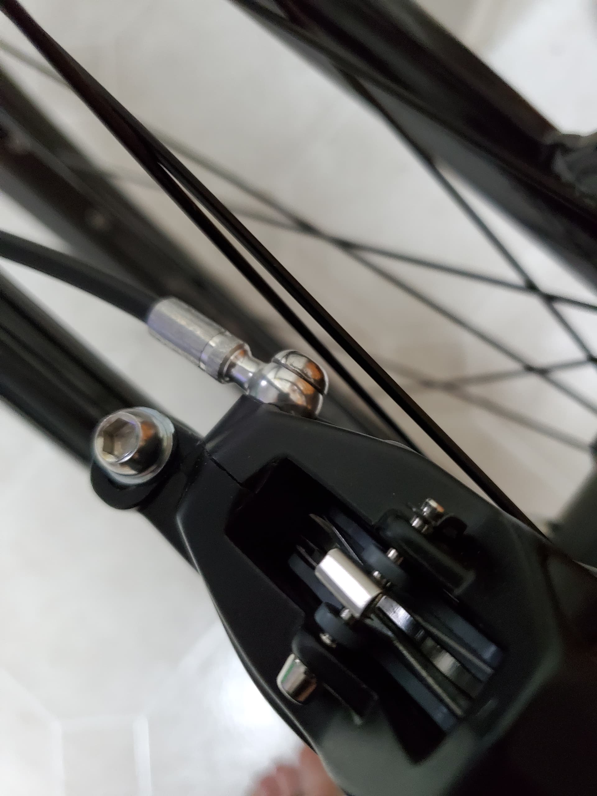
The spokes are a bit of a problem. The non-disc side outer spokes are going to be passing very close to the inner Nimbus frame tube at the hub end of the spoke (as others have also found). So maybe some spoke head washers for the inside heads, or filing or denting the frame (or maybe as long as no spokes actually hit the frame, it will be fine).

I had some DT Swiss Champion spokes cut to size (with a generous thread length just in case), matched with brass 16mm long nipples. But there would be problems with spokes which had the heads on the inside of the flange (particularly the thicker disc-side flange), because they have to bend quite a lot to get to the rim spoking line. This is exacerbated because the J end of the spokes are quite short, as bicycles these days have thin flanges. Luckily I had the old spokes, so I am getting half of these recut and threaded, as the J end on the old ones is nearly 1mm more, giving the spoke room to move. It might look a bit “interesting” with some spokes black and some silver. And I think I will also spoke the disc side the “wrong” way (spoke heads in the dent) to give even move room for the elbow to clear the flange side so it doesn’t have a curve (i.e. a stress region).

[EDIT: I actually put all the spokes in the “right” way (shoulder in the dent) and I noticed that the 9 outer spoke heads on the non-disc side were good candidates for a brass washer.]

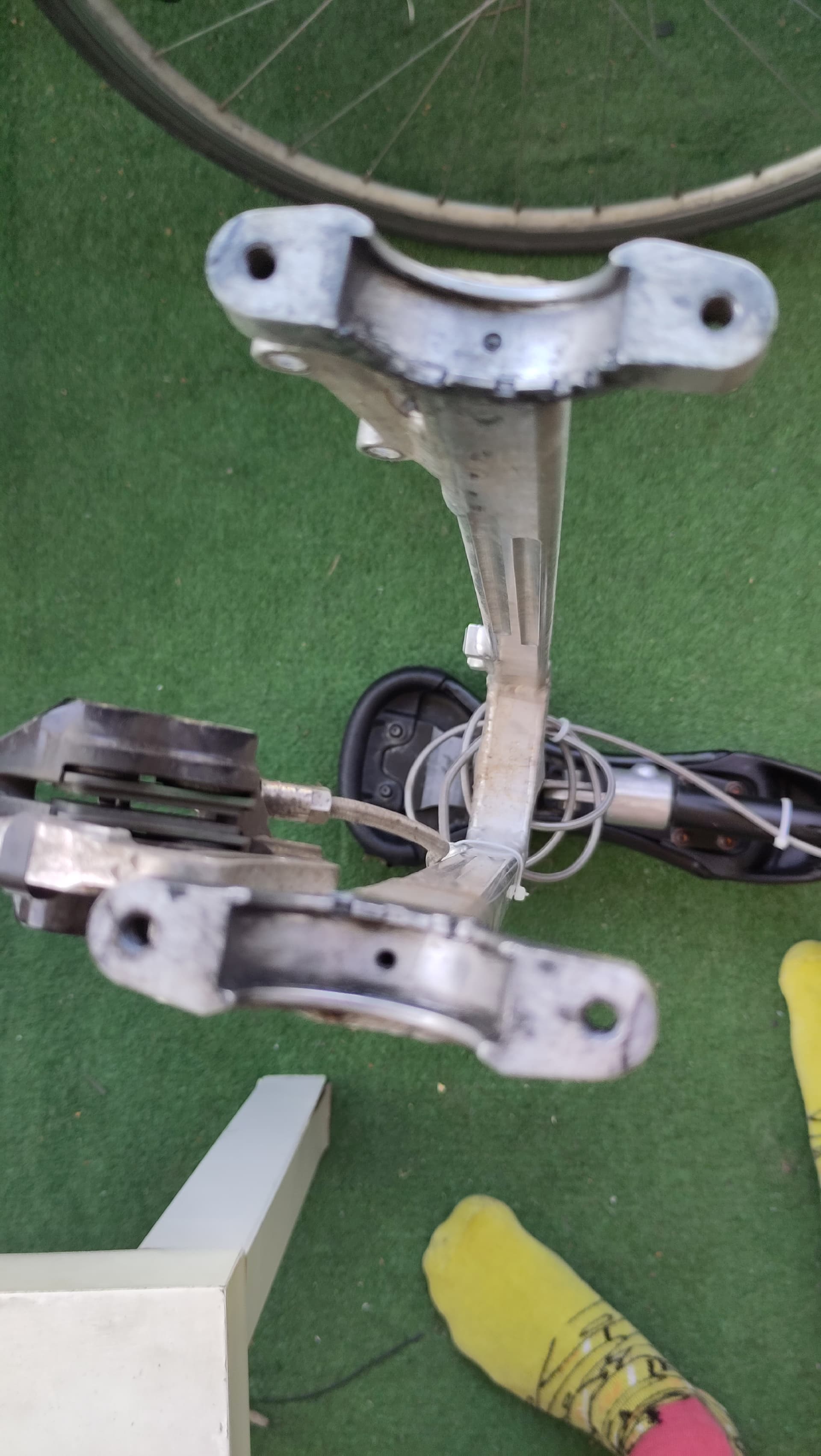
For my wheel lacing and truing job, I have attached a cross board to the shadow handle so the frame is steady and stable when inverted on the seat and handle.

When I get to putting the 150mm cranks permanently on, I am currently thinking (hmm) I won’t bother with a spacer, as maybe it could just push into that small bearing protector that is already on the hub. I will also be careful with the bolt (learning from the experience of those coming before me!).

So that’s it so far. I probably won’t finish it for a while due to imminent holidays. Good luck to anyone on the same journey. Sometimes I think “why did I do this? my Nimbus Oracle 27.5 is the perfect unicycle”, but then if I didn’t try the Schlumpf, I would have always been wondering what it would be like.

6 Likes

Great to hear all your insights into these newer variant hubs. Will be interesting to see a 125 build and how it looks / rides

I confess I often think this during the first 30 minutes of riding mine in high gear. Am I mad? I say to myself as it isn’t as relaxing or as easy as my fixed wheels. Especially when my heart rate hit 190 riding up a long gradual slope in high today. Sure it was probably a good deal due to nerves and general fitness issues. But it can be over taxing. I stopped and took a moment to chill and unwind the brain.

And then there are the moments when it feels comfortable and COOL and just a full on different experience - and I have no regrets.

I’ve in fact learned to never let the doubtful moments make me regrets or critique my choice in getting into this weird and wonderful area of unicycling.

3 Likes

Hi all! Just wanted share the details of my recent Schlumpf build for anyone else who is planning a build, especially a 36" wheel.

My hub is a 100mm 36H with a 203mm disc which I built it into a 36" wheel. Below is the parts list:

Frame: Nimbus Oracle Universal 36" Disc Frame
Rim: Nimbus 36" Stealth2
Spokes: Unicycle.com 367mm 14ga spokes, cut to 359mm
Brake: SRAM G2 RSC hydraulic brake
Saddle: KH Fusion one
Cranks: 125mm Nimbus VCX
Tire: 36" Nimbus Nightrider Lite

Regarding the frame, the Nimbus Oracle Universal 100mm frame worked pretty well. On initial lacing of the hub, there was some interference between the spoke j-bends and non-disc side of the frame, however this was resolved after the spokes were tensioned. The frame came with a small weep hole in the center of frame side bearing holders. I used the bit provided by Florian to increase the diameter of this for the anti-slip tab on the hub.

When mounting the brake caliper, there was definitely some lateral clearance issues. Initially the caliper was not clearing the spokes. Florian sent me the 1mm rotor spacer set and I ended up using all of them to get the caliper to clear the spokes (3mm total addition). My hub was built prior to the recent change that gives an additional 2mm, so I think others might be able to get away with less spacers. I also switched the rotor bolts out to a lower profile M4x14 button head hex bolt to avoid the issue of the bolt heads hitting the frame. These work pretty well, but the key depth is fairly shallow, so it’s easy to round out the bolt :grimacing:.


Regarding crank install. This was my first time installing cranks on a hub. I used the provided bolts to pull the cranks onto the spline. There was definitely some rounding/deformation on the crank bolts as I tightened them up. Seeing the deformation, I only tightened to 40Nm. I didn’t have any spacers so I didn’t install any between the cranks and pressure rings. At 40Nm the gap appears to be ~2mm. Next time I change cranks I may install spacers if I have some on hand.

Overall I think the build went well, despite some of the clearance issues with the disc brake. The wheel itself is definitely heavier than my ungeared 36er. When riding, I can really notice the increased inertia from that extra weight. This is my first geared unicycle, so I’m still learning how to properly shift and maintain balance in high gear. Last night, I started being able to successfully shift without UPDing, which feels awesome. The gear mechanism feels very smooth in both high and low gear. There is bit of play in the pedals that you don’t get with an ungeared hub, but you stop noticing it after awhile. Riding in high gear is a bit harrowing, but somewhat reminiscent of when I first started on my ungeared 36er, so I’m sure I’ll eventually get used to it :grinning:.

Remaining actions on the build:

  • Shorten brake cable, this is purely cosmetic.

  • Figure out where to mount a cadence sensor. On my ungeared 36er I had it mounted on the hub, but with the Schlumpf being much wider, this is difficult. There also isn’t a lot of clearance between the cranks and frame for this either.

  • Continue retorquing crank bolts after each ride. This is getting better, but I definitely recommend using a torque wrench to retighten the bolts after each initial ride with new cranks.

  • I’m going to try to find a standard ISIS crank bolt that I can use in the future for pre-torquing cranks. I’m a little disappointed with the deformation I saw in the provided crank bolts on install. I believe these are M15 bolts, which may be a commercially available ISIS bolt size (just not with thru holes for the shifter buttons). I also ordered some spare bolts from Florian, just in case.

  • I may eventually try out longer cranks (maybe 137mm) as the 125mm are a bit short for my feet. I’m a size 10 and I find the shifter buttons fall in line with my ankles rather than my heels. Thus I’m finding myself shifting via ankle roll rather than heel click.

  • Change pedals. Right now I’m using some Nimbus studded plastic pedals that came with another unicycle. I want to eventually swap these for clipless, but until I build up the courage for that, I’ll probably install a set of Race Face Chesters.

5 Likes

IMHO, you should probably try clipless on another uni. Starting on a G36 may be dangerous because of the height and the speed.


Question for those out there that have already drilled their frame: do you think I should drill through the already-present hole in my Flansberrium frame? Or should I drill a new hole? Maybe @jaco_flans has an idea about that… :slight_smile:


Cool socks, aren’t they?

4 Likes

I confirm it’s safe to drill :slight_smile:

(The socks are nice! )

4 Likes

Do you always wear the same shoes? When lined up front to back the Wahoo cadence sensor can go on a shoe - that’s how I get mine to work on all my unis and in low or high gear.

1 Like

I used to use that exact sensor + setup, but I lost it after a UPD. :laughing: The plastic mount split and the sensor went flying off the trail to somewhere I couldn’t find it. Since then, I mounted the replacement on the hub. I might try attaching it to one side of my pedal.

Agreed. I run clipless on my bikes, but I definitely plan on trying it out on my smaller wheels before the geared 36er.

3 Likes

Loved the build detail on this! Looks very stealthy.

Re this: - would be amazing if you and others experience this we get it clearly fed back to Florian.

I did with my install and I kind of got short shrift by reply - in other words I wasn’t really believed:

Response Quote:

That the axle bolt made of one of the toughest materials available deforms is not possible. You should first push the shift shaft through so that the key grips in its full depth. With a good wrench and proper fit, 55Nm is no problem. We have over 30 years experience with this material and torques. 10’000s of bicycle hubs had even smaller Allen size and were tightened with 55Nm.

I respect much of the responses from Schlumpf HQ, but with this point I was a bit disappointed, but now it is kind of reassuring that this isn’t a ‘just me’ issue and if feedback is given perhaps we can get an official pre-tightening bolt as you’ve outlined :smile::crossed_fingers::gear:

3 Likes

The material that the screws are made out is only part of the story. If they are not properly heat treated after manufacturing they could very well be too soft. All socket head cap screws have to be quite hard.

1 Like

Just got back from a ride and retorqued the bolts. Here’s a photo of each showing the deformation from the original crank arm installation.


I don’t expect I’ll have any issues backing them out if I need to change cranks, but I probably wouldn’t risk using them to install a new set of cranks. I placed an order for a couple extra pairs of bolts from Florian last week.

I can’t say with 100% confidence that the deformation isn’t user (mine) error, as during the initial install I used a 1/2" drive adjustable torque wrench which required a 1/2" to 3/8" drive adapter between the wrench and the provided 8mm key. The multiple connections there had a bit of play which may have contributed. I’ve since switched to using a 3/8" drive torque wrench (Park Tool TW-6.2) so there is no need for a drive adapter.

I didn’t think to measure the bolts prior to installing them, and I’m not going to remove them now to check, but I think they are M15 bolts. I’ll confirm when I receive my spares in the mail. If so, I’ve seen a couple M15 ISIS bolts available online, that I might try next time as a pre-torque bolt. FSA M15 Crank Bolts - Amazon

2 Likes

You must install spacers !

1 Like

Me personally - I agree, but when queried with Florian due to there being such a large gap (in my view therefore needing spacers) I got this reply:

Why use extra spacers to contact the crank stop rings?
We make these rings so that when the cranks are mounted repeatedly and get closer and closer to the center of the hub, they protect the ball bearings behind. Normally they have no function.

I have used 2mm spacers and feel personally happier to have some pressure holding the cranks snug to the hub’s inner bearing area. But then again, it seems like officially this isn’t how the pressure rings were designed.

:man_shrugging:

1 Like