The problem I see with a flared top to whatever you’re inserting is that the hole drilled in the frame is on a curve, so the shim/bushing would need to be also shaped to fit that curve unless your intention is that inserting the bearing with nub will deform the shim to conform to the shape required. there also doesn’t appear to be any real chamfer on the hole in the frame.
I’m now firmly in camp of drill a hole in the bottom of the bearing housing though. Easy to replace, and easy to keep an eye on. If you’re anything like me you already have spares.
Something worth remembering too is that now the disk is on the hub, the forces from braking are no longer through the reaction nub/knurled bearing, which in my experience was the most common reason for having them slip.
Sure, hard acceleration with long cranks in high gear can also be quite a lot of force, but nothing like a hard brake assisted stop.
I agree a hole in the bearing cap would be an option also. Maybe not as strong as using the hole in the frame and maybe harder to get the hole exactly in the right place but doable with some care.
With the flared bushing in the original hole frame, if the chamfer is not large enough it could easily be increased a little with a countersink reamer. The increased diameter of the flare on a custom made bushing would only need to be very tiny to prevent the bushing form slipping into the frame. Also with a custom made bushing the length of the bushing could be made longer then the the pictured/supplied bushing to take advantage of the entire surface of the original hole in the frame.
As finnspinn said use loctite 648 to glue the bushing into the frame. I built a complete unicycle frame with loctite and it held up quite well. Post a picture of your unicycle(s) - #273 by ernst
Another option would be to cut the bushing parallel to the Rotation axis. Then you could bend it a little bit so that it fits tight to the bearing.
If you don’t want to cut the original bearing, you might find aluminium tubes 8mm x 6mm to cut bushings from it.
I’m being convinced to try this option - for some reason I’m still resistive to go the bearing cap drill option as it niggles me that this isn’t the way Mr Schlumpf designed things or is expecting people to drill their frames.
Genuine thanks to everyone so far for such detailed and thoughtful responses.
I know we’re getting into the weeds here (off topic), but would Loctite 638 work as well as 648?
I have 638 already and 648 seems very hard to find in small bottles here in the UK
In the absence of the new manual; does anyone know if additional crank spacers are required with the 2016 version? I tried torquing the axle bolt to 40Nm (as mentioned in the 2016 manual), but there seems to be roughly a 3 or 3.5mm gap in between the crank and the delivered spacer.
That’s interesting to see that it doesn’t fit flush at that torque.
I’m presuming you used the torque setting bolt supplied? And gave it a good whack with a rubber mallet?
I can’t say I know if one should or shouldn’t use extra grease, but that might help it seat.
It would be nice to know if we can go higher on the torque side of things, but I’m thinking that perhaps the torque setting only “matters” when it its butting up against the spacer.
I’m also thinking these hubs could have been built in a much tougher way so that in fact to get the cranks on it takes much more initial tightening.
This is all just conjecture, but the fact remains you don’t want that space.
It’s now a question really for Florian -
A) can / should we torque cranks until it touches spacer
B) if gap, should we add in our own extra spacers
Now… I will apologise before I give you my suggestions since the first might cause you to hyperventilate or start to catatonically rock back and forth at the very suggestion… If it were my hub, I think I’d go with the second approach in the first instance, it could be a bit messy though. I’m also assuming the spacer is flush with the top of the nub-on-the-hub when it is fitted in the first approach.
I don’t think I would trust the glue to attach the spacer to the spigot. In the past I have glued large bearings (~90 - 100mm diameter) into worn cast iron housings with Loctite and they’ve been just fine under some pretty heavy loading radially and axially. However there was quite a big surface area for the adhesive to bond on. In this case you have minimal area, and any movement of the hub in the shell will be affecting the bond. I can just imagine the day you take the thing to bits and lift the hub out and the spacer comes off despite the glue and your fears are realised and it ends up inside the frame and you end up having to drill a 1/2" (!) hole to get it out (I have lost nipples inside carbon rims in the past and they are a nightmare to get out, this would be similar I think without a suitably large hole).
First suggestion:
I think I would take a belt and braces approach. The first thing is similar to your expanding foam idea. I don’t like the idea of expanding foam, but I would go with some glassfibre reinforced body filler (like Isopon P40). Mix a little of that up and hook it in through the hole in the frame with a piece of steel wire (~1mm) with a short 90deg bend/hook on the end and smear it onto the inside of the frame so you can build up a mechanical barrier. If you were brave and had built up enough of it you could insert the spacer into the frame and let the glassfibre filler set up – it might need some cleaning up but it might just hold like that.
However, I’d probably just build up some filler on the inside so that if the spacer were to 'fall in" it couldn’t really go into the frame, this is the ‘backup’ is case it ever came off…
Now for the part you won’t like I would put the spacer onto the spigot on the hub and with a reasonably sharp centre punch put a four centre punch marks at 90deg spacing round the joint(on the joint) between the spacer and the spigot – nothing too heavy or you’ll deform the spacer, just enough to give it a mechanical fixing. You’d get it off if it ever needed to come off. This is a tried and tested way of securing such things, it would rely on the top of the spigot being more or less flush with the top of the spacer though.
Second suggestion:
This one might be slightly more palatable and doesn’t touch your hub at all It is in the same sort of category as your foam suggestion and is a refinement on the first part of the first suggestion above. It would use glassfibre polyester or epoxy resin (so pretty fluid/flowable) to create a plug bonded to the inside the frame . Here is my thinking out loud approach:
Mix up a few millilitres of resin (say 10-15cc per side)
Stick the spacer on a piece of tape (say electrical tape) so you can tape it into the hole in the frame and it won’t fall in).
Make a hole thought the centre of the spacer/tape so you can get the tip of a syringe though it.
Stick the spacer into the hole with the tape securing it so it doesn’t go in
Then with the frame vertical and the correct way up (ie the bearing holders at the bottom), slowly inject the polyester resin up into the inside of the frame with a syringe so that it will flow back down into the inside of the frame and form a plug at the bottom.
Then quickly take the syringe out and put another bit of tape over the hole to seal it up until the resin cures.
Then pull the tape off and clean the hole up with a 6mm drill…
With any luck you’ll have a plastic plug formed inside the frame, with the spacer bonded in place and no way for it to go inside the frame.
Your mileage may of course vary, and you might have some sticky mess to clear up, but…
Thanks so much DrD! This is all really useful points and suggestions and I kind of like both options you’ve suggested.
Sure I did wince at giving my hubs a sharp whack with a centre punch a bit, but never say never - although there’s just something neater about having the already prepare shim attached in the frame and providing a 6mm hole… as nature intended
You’ll probably shudder at the banal suggestion now from me, but after thinking about using a resin or the glass fibre stuff inserted in, I just wondered if I’d be safe to use say silicone sealer - bit like the stuff you get to put a line around your bath or sink. But of course something that isn’t bad for aluminium.
Weight penalty could be there as I guess it isn’t that light once I’ve filled up the entire fork leg - but…
Having said this, I am swinging back round to your idea of a resin injected in and letting gravity flow back down to seal in shim.
The ones you’ve suggested I suppose are safe to interact with aluminium? How viscous are we talking? I’m just wondering if it would run slowly enough to ensure that there isn’t a flow into the bearing mounts surface, as naturally I’d like to keep that uniform and without any additional layering up that might impact the bearings themselves by added extra pressure.
This idea seems the neatest so far as it would provide a sealed plug and the shim would be baked in there.
I’ll have to chew it over, while I also think long and hard if I’ll risk trying the loctite option into the frame itself - as while I’ll be careful the risk of losing it in the frame still haunts me!
I think silicone would be too viscous to flow. back down so you’d have to fill the whole thing, which I don’t think would be a good idea. Also I think that it is air curing so it wouldn’t set (it would be just like being in the tube it came out of.).
Folk cast things in polyester resin for artistic reasons, so it follows quite well – getting some of the stuff used for that would be the stuff to get – search for ‘casting resin’ – you’ll probably find lots of videos of people doing such things (haven’t looked). You can probably thin it as well, I haven’t looked into that in any detail.
If you did get resin leaking out onto the bearing surface you’d be able to cut/chisel/scrape it off back to the aluminium surface once it has cured so it shouldn’t affect that in any way. If you did do this, mask up the outside of your frame by wrapping it with masking tape – you don’t want any of this getting onto the outside of your frame. Polyester resin is soluble with acetone before it cures to you can clean stuff off before it cures, after that it would need to be mechanically removed and you don’t want to do that on the outside of your very nice new Flansberrium frame!
Bear in mind there is significant chance of making a mess with this stuff, you’d need to use a syringe with a reasonable bore on the end, but a 30-40cc disposable syringe would probably do the job in one mix. I’d try it to make sure you can get the stuff out before mix any hardener into the resin (don’t put anything unmixed into the frame though).
This stuff is completely inert as far as I know, it is slightly exothermic when it is curing, but if you are only putting a relatively small amount into the bottom of the frame leg I think it would be fine. I wouldn’t go filling up the whole frame with it – as well as the heat generated when it curing it would affect the mechanical properties of the frame when it is solid.
Silicone sealer gives off ethanoic acid as it cures (hence the vinegary smell) so I would avoid putting that into your frame for that reason as well.
Anyhow, this has all just been pretty dynamic thinking at the keyboard, but it might be the germ of an idea to get you sorted out without resorting to welding up the hole and (probably) milling out a 6mm hole and dressing up the inside of the bearing holder with a die grinder… I do think that would be the best overall solution but not the most practical without an AC TIG welder and a milling machine
Thanks again everyone for the help on this small but what appeared tricky issue.
I may still do the resin option suggested by @DrD but when I got round to using Loctite 648 (got some in the end!)
It wound up being a really really snug fit. The spacer Florian created was really hard to press into the 8mm hole and in fact it probably could have been left as a friction fit.
When I’d first tested the shim out I got the impression it could easily fall through into the frame leg.
My belief now that with the right fit and this loctite it ain’t going no where. Not least as I don’t believe it is directly under any load or major jostling. The odd bit perhaps from the nub holding back the torque reaction forces but this will be more like a press up / down to its 12 and 6 o’clock as it were.
They’ve both gone in nicely to my eyes and they’re just a hair lower than the surface of the bearing mount - which for me feels like a good thing so nothing is pressing on the bearings themselves.
I’m not likely to be installing wheels in these frames for 48 hours + so there’s lots of time for that to cure.
Anyway, thanks once again all for the suggestions and to those that have helped fix this shim-nanigans
With the new hubs - do we think the guidance from the old manual stands true?
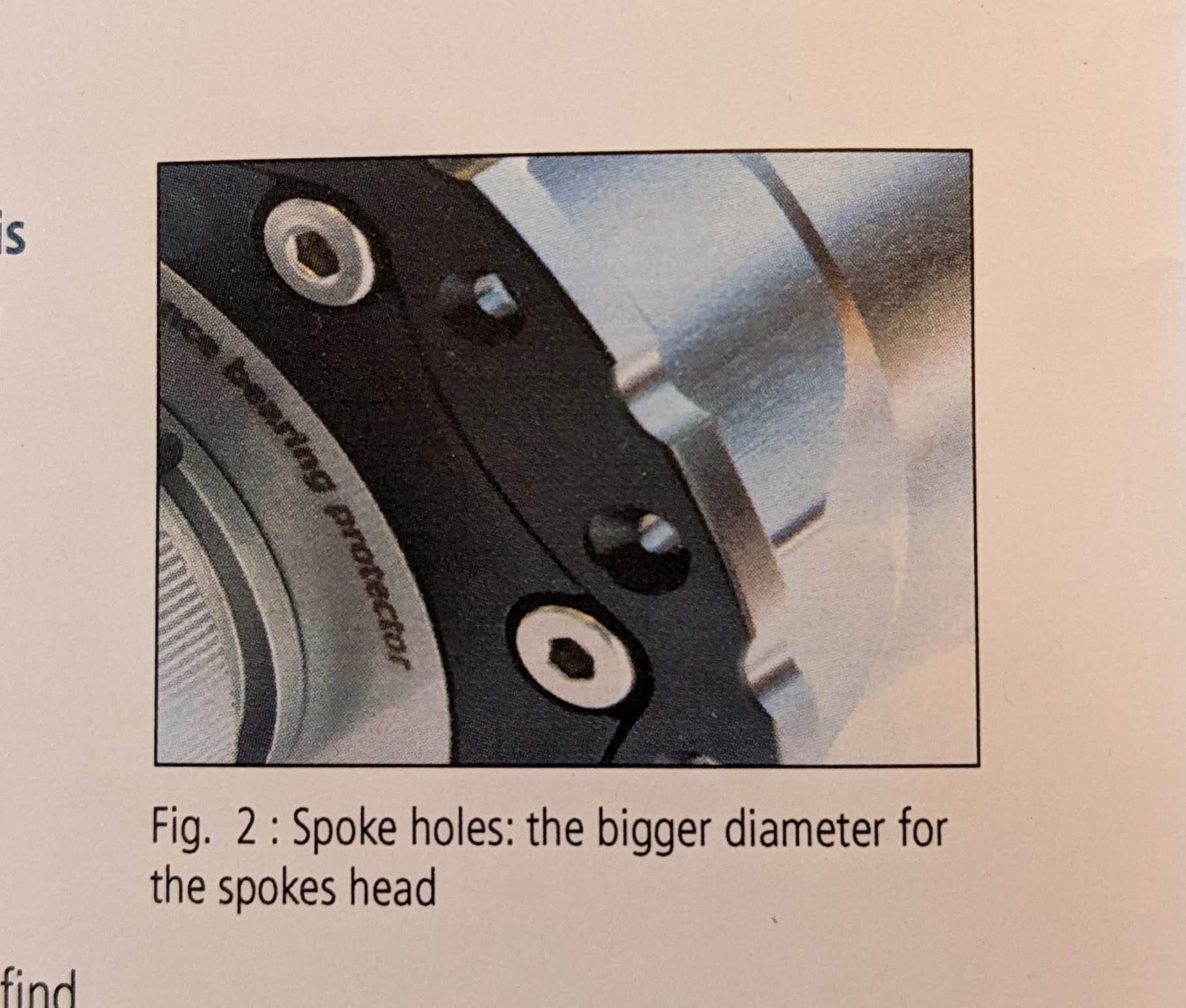
Spokes —The hub has 36 spokes holes, designed for 2mm spokes. Check the direction of the spokes! The bent part must be positioned at the countersunk section of the spoke hole.
I ask as looking at the hub you’d instinctively install the heads of the spokes into the countersinking area.
I know we need a manual but I would really love to know peoples views.
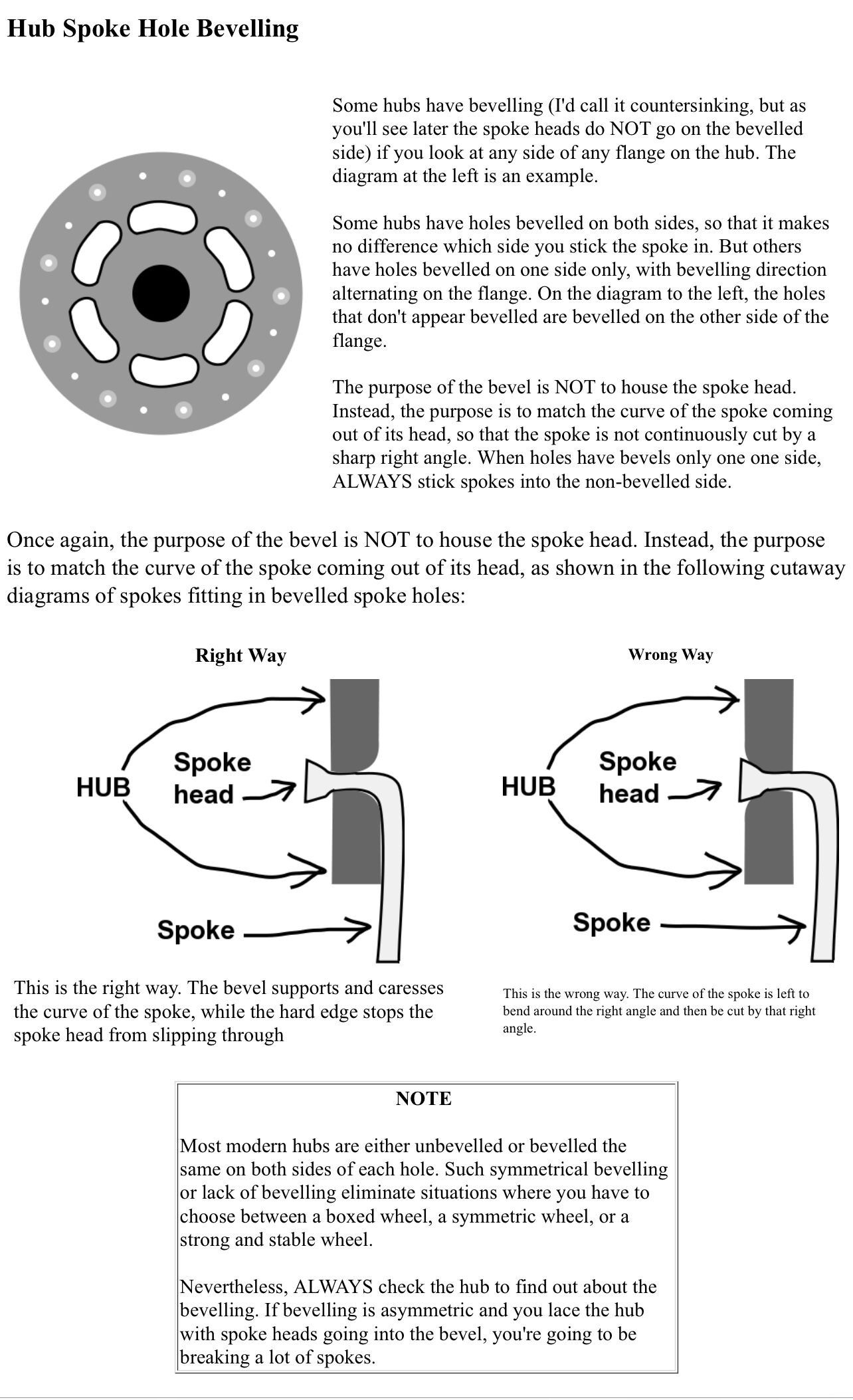
This kind of contradicts the first bit of advice. But perhaps the point here is that for a hub where not all the holes have countersinking, then the holes that are countersunk are for the J-bend to not sit on a hard edge.
I still haven’t heard from Florian but I do have it on good authority that the spoke heads need to sit on the flat side, with the J-bend being on the countersunk side.
If I’d have built these wheels myself I’d have gone the other way, based on the visuals of the countersinking matching the heads of spokes. Hopefully this helps people avoid a rookie mistake with lacing etc
(Still curious what Florian says, but I now highly doubt he’ll go against this clearly understood wheel building principle)
That was a good find! There is a pdf of the advice that was shipped with some hubs a few posts on from that, and a little further on a good analysis of the issue:
I’d read it some months back, but only today went and looked at my 400 series hub that I laced 2 years back and realised Ive done it the wrong way! Those countersink are so inviting to put the spoke heads in and it looks so neat afterwards!
Now I need to decide if I’m going to rebuild the wheel - I’ve probably ridden it less than 500 miles…
They’re even more inviting when there are zero smaller countersunk holes on the off-holes. Meaning when you see holes that look like spoke head recesses, and holes that have nothing - you’re even more likely to think: ah ha, that’s when the heads must go!
I had a bit of a deja-vu feeling about all of this, not from the Schlumpf perspective as I don’t have one, but from other hubs, remembering how much better the spoke seemed to sit when the bend was in a countersunk hole.
It is a bit surprising that there isn’t a countersink on each side of the flange. I’ve built a couple of wheels with Schmitt hub dynamos (look for pictures of SON hub dynamos, eg the SON 28) – they have pretty deep countersinks on the outside which are exacerbated a bit because of the inward curvature of the flange. I seem to remember thinking that the J of the spoke sat pretty well in those countersinks. On the spokes with the heads on the outside they sit pretty well in the deep countersink but there is a shallow countersink on the inside as well for the bend. I had a look at one of the wheels and the spokes do look like they sit well at both sides of the flange.
I also had a very quick look at my Pipfax hub, which is still unbuilt for various reasons, and it has a countersink on each side too. I had a quick look at a Hope Pro4 rear hub and it is a bit difficult to see because it is built up and has a cassette and disc on it, but there is a slight countersink, maybe more of a debur/relief on each side of it.
Putting spoke washers under the heads on the un-countersunk side of the Schlumpf. as suggested by your wheel builder, is really a bit like providing a countersink I suppose!