Another screenshots showing what it would look like in compression.
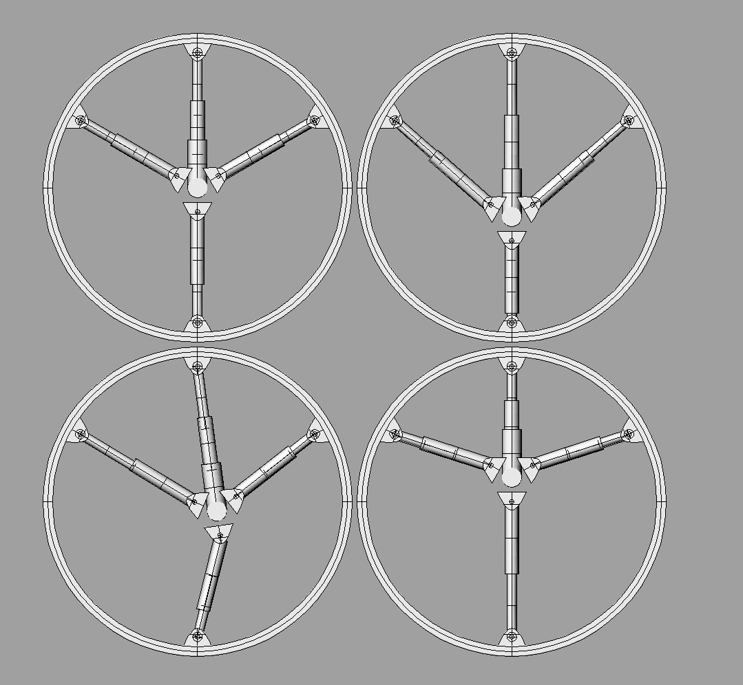
Ok, someone has to see this and tell me what you think!
what orientation would the pedals be? If they were parallel to the rigid shock then surely nothing would move in the way it was meant to, and something would end up breaking?
I shouldn’t think it;d break if the pedals were parallel to the not-really-a-shock. Looks like a pretty cool idea, my only thoughts being if one set of telesocping metal tubes will be strong enough to transmit all of the rotational forces.
The other problem with all thse is that adding 3 shocks to a wheel will be very expensive, and will weigh a lot.
Nice ideas though.
John
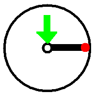
This calls for a diagram…
Say you were hopping, if the cranks were parallel to the shock, then the shock would be horizontal. All the wight of the rider (the pretty green arrow) would be transmitted along the shock, and the rim would all hinge around the other end (the pretty red bit). Common sense and physics tells us that, just for the purposes of hopping, the whole thing would work better were it hinged at the hub end. Unfortunately bitter experience tells us that with the forces involved, the chances are that something will bend or snap.
Most of us have had problems with cranks bending, there are two of them to spread the load over, and they’re only about half the length that this shock would be, meaning there’s much less leverage involved.
prettypicture.bmp (111 KB)
The extra bit isn’t a shock, the idea of that (I think, apologies if wrong) is that because the hinge is at the rim end the hub is no longer free to rotate within the wheel, avoiding wind up.
The 3 shocks will still take the majority of the weight of the rider and the force from hopping. The telescopic bit would transmit rotatioanl forces from acceleration.
In the situation you describe, when you press down on the pedals the telscopic not-a-shock would extend slightly and tilt down at the rim end, so that the hub will move downwards in a vertical line. It’d tilt backwards a bit as well, but probably not by too much. The load would be taken by the shock absorbers either extending or compressing.
John
P.S. this is a great distraction from revision. Pity the exams in just over an hour. Ah well.
Yes John, that is what I am saying. ALL your weight would be on the three shocks. ALL the rotational force would be on the telescoping pole (its not really a shock so I’m going to stop calling it one). When you go off a jump the telescoping pole would bend at the rim and extend, or compress. There would be no pressure on it. ALTHOUGH if you go off a jump and the tire wants to rotate, then you would get pressure on it.
Other notes. There is no reason not to use more shocks except expense. And the hinges might not like sideways forces. Perhaps attach them the same way as spokes, at an angle. This would require more shocks though. Or perhaps extra geometry that does not support the suspension, but prevents the rim from buckling sideways.
The point I’m trying to make, although I’m not very articulate in saying it, is that, because the telescopic pole is fixed rigidly to the hub, and hinged at the rim, if the pole were horizontal to the ground, then (hopefully) the pole would not be able to bend upwards at the hub, and it would not be able to extend or compress, because the force would be on a different plane, and so the wheel would be forced to hinge around the end of the pole.
If you’re hopping with the pole horizontal, then your weight, acting downwards on the hub, is effectively rotational force on the pole, and we know from bitter experience that the forces involved in trials, muni, and hopping, are enough to bend and break even the best equipment.
One of your screenshots seems to illustrate the situation I’m trying to describe, In the pictue it shows the pole bending downwards but it doesn’t take into account the fact that, when you’re hopping, you’re standing on the pedals, and keeping them horizontal.
Basically, it’s a very good idea, and I’m sure it could work, but your drawings don’t seem to take into account any of the torque that would be transmitted through the metal pole, and because in the drawings the hub can rotate freely, the pole behaves as it would if it hinged at both ends.
Would it be possible in the software you’re using to make it so that the hub can’t rotate?
How easy would it be to model the wheel actually in use? i.e torque on the hub, weight visibly acting downwards, ground visibly acting upwards.
It is of course perfectly possible that you’ve address all these issues, and I just can’t see it, in which case I apologise for wasting your time.
personally I think you desgin a fully enclosed unicycle, because I have to ride down to the supermarket now and its just started pouring with rain.
A problem I see with all of this that hasn’t been addresed is if you have ridden a suspension bike, when you get on your weight compresses the suspension. And with the suspension wheel the hub would be out of the center of the wheel or the springs would have to be tuned exactly to your weight to make the hub in the center of the wheel or I think it would cause a lot of extra resistance. And I think it would be great for drops, but unless the suspension was springs only it would be awful for trying to hop, as bike suspensions are dampend and it would absorb most of your hopping energy. and if it wasn’t dampend the suspension wouldn’t work very well on the trail. And another thing it wouldn’t work with rim brakes but I guess a disk brake would work.
That is an excellent point and not one I considered. If the telescoping pole was a parallelogram then it could move up and down but maintain its horizontal orientation. This would make that part much more complex though. I’ll see about changing my model.
If you are asking about an animation, I can’t do that with this software. If you are asking about rigging it up and then adding forces to see what happens, that I also cannot do.
Here is what i mean. It would work like an A-arm. The parallelogram is hinged at all 4 corners. And would of course still telescope, i just didn’t model that.
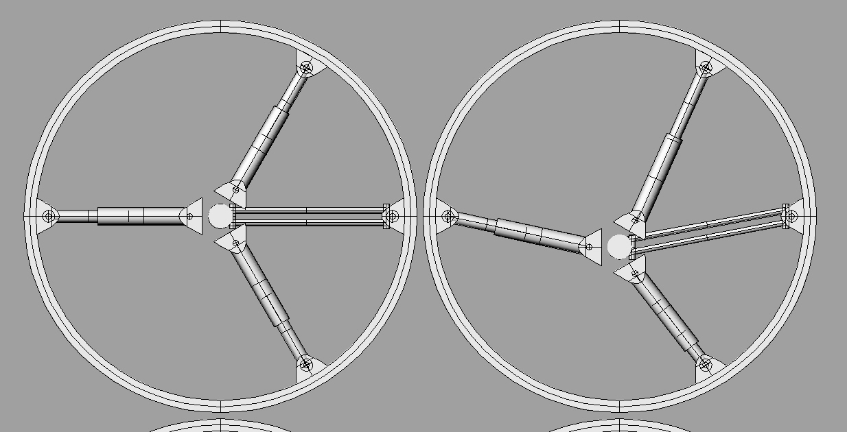
It keeps getting more interesting. Rayden’s design is really different, and it’s hard for me to picture the forces involved. I can see that each addition of more moveable joints and other parts is going to up the weight, but let’s not worry about that and stick with the theory of making the design work.
The main problem with Rayden’s design, and I’m surprised nobody has mentioned it, is the non-suspended spot in the wheel. Each time you hit the non-suspended part (with the rigid arm at the bottom), you won’t have any suspension. If your suspension is compressing from rider weight, you’ll have a big hop in the wheel as you go over this spot. I guess there would be some amount of hop at the opposite side from there as well. So it would be like riding on a non-round wheel.
You could keep the suspension pretty stiff, like what I have on my Wilder’s seat post, but then you won’t get as much benefit from the suspension action. This is probably fine for cruising on bumpy stuff.
Using shocks would be more for riding and dropping, and less for hopping. For dropping, it’s important that the rigid arm not be perpindicular to the pedals!
Unfortunately I think the non-round issue would be the big problem, before one would get too worried about the strength of the rigid arm. That weakness could be covered by building it to larger specs. For cranks and axles we’ve been working with existing bike parts. For the wheel we can start from scratch.
I think the idea is that while this arm will not have any damping or rebound it will still be able to compress. The only thing it can’t do is rotate around the hub, being fixed to it.
If you were doing a stationary drop it might as well not be there, it offers no support so the hub is free to move around within the wheel; it’s only when you start pedalling that the hub will make this arm rotate around it, so turning the wheel.
Would it work with the original three-shock design if one of the shocks was connected directly to the hub rather than them all being hinged? It would save a bit of weight…
Phil
John, the rigid piece telescopes. It can get longer and shorter. It would do this any time the wheel is compressed, whether this piece be vertical or horizontal.
As far as letting one of the 3 shocks act as the rigid piece, I think it might affect the strength of the shocks depending on orientation. Although I’m not certain of this and it might work. But you would get the problem I think i fixed with the parallelogram design. And adding a parallelogram to a shock would be much more difficult.
Aah. Much better!
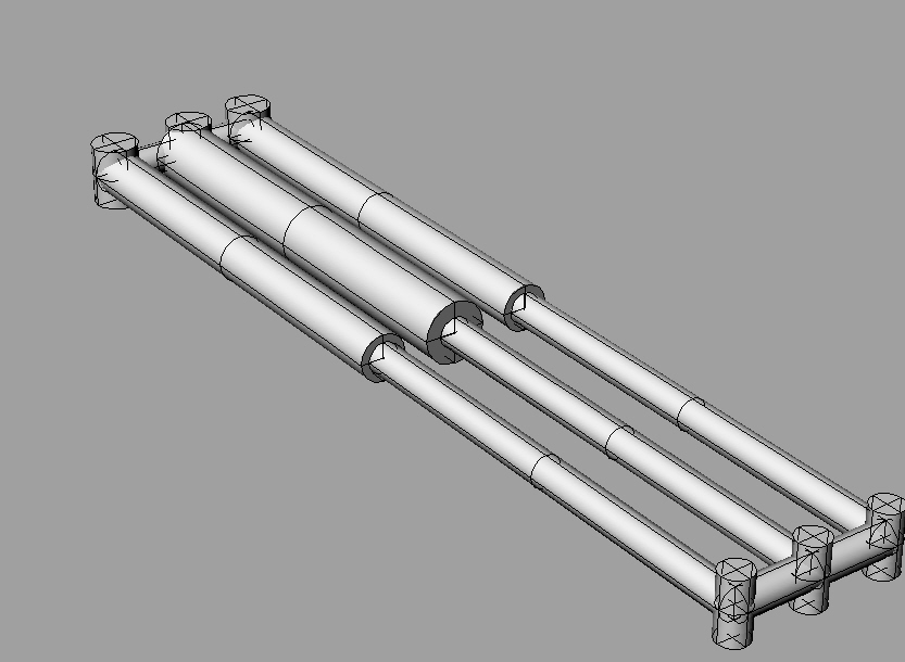
The key is the parallelogram. There is no need the rest has to be shocks. They could be strong, stiff rubber bands done like this.
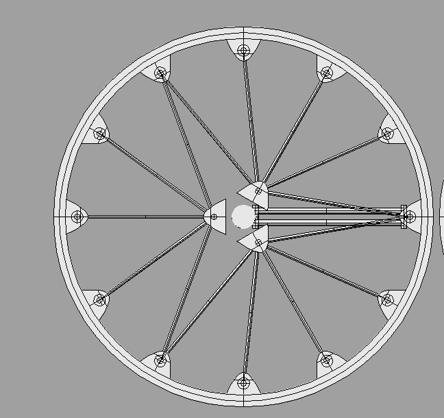
Close up of what I think the parallelogram would look like. This one has a shock in the middle of it. Each vertical cylinder is a hinge. I’m not so sure a shock in the middle of the parallelogram would be good though. It would have to be tuned differently due to its alternate length.
UR UNICYCLE SUCKS!!
Actually i just want to be able to do stuff like that on my p.c great idea would be really funny to see!
Ben
Ok here is a question. Shock absorber versus spring. We have all been assuming shocks would be better but why? There has to be a reason. Of course we could build a protype of each and see but I dont think that is going to happen.
I think there needs to be some sort of shock absorber or we would be bouncing all the time. But what if we used a bunch of springs (springs could be physical metal coils or rubber bands. anything springy) but then add 3 small dampeners. This might be lighter than 3 heavy duty shock absorbers.
I’ve been assuming something like on bike rear suspension, which is a spring (either air or coil) and a shock absorber in one unit.
It’s possible that something could be designed for a uni-specific shock/spring, but I don’t know how it would differ from a bike shock, or if the extra cost from low production numbers could justify the improved performance.
John