Overall the concept looks workable except the chain system which looks problematic.saskatchewanian’s suggestions looks to be a good idea to get around the chain problem.No doubt there are still many details for you to work out but if you get the fundamentals right all the other fiddly bits can be worked out in time.Keep at it.
Ok guys also, I’m like flat broke, so im not spending money on it lol… I’m scavanging parts from my grandpas huge junk pile, and a metal shop thats free for me to use, minus metals from there. thanks for your help though guys
and also, Isnt the whole point of what i drew to have the tire free traveling? Minus some small flaws in it, initially, replacing some things with springs, and supporting other things, ive created somethign that can move the tire without moving the pedals, duh! lol:p 
Edit: When i do this, im going to re-inforce my pedal frame and stuff. I might weld more metal on it or something, to keep it stiff. Also, when i do this, im going to need to figure out how to tig weld things to the berrings, but eh, i think its going to work out all fine
I don’t think that the shaft drive would be all that expensive. A telescoping shaft might be a bit harder to find for cheep but it should not be hard to find cheep bevel gears. If worst comes to worst you could use two different sizes of square tubing for the shaft but then you would need to get creative with attaching bearings etc.
I will be interested in seeing what you end up building.
edit:
Not quite. When the shocks are compressed your chain tensioner is going to lengthen one side of your chain while shortening the other. If your tensioner is on the front of the frame this will turn your wheel backwards, or if the tensioner is on the back it would spin the wheel forward. And vice-versa for the cranks.
As for unicycle shock absorption for trials, I have always been a fan of adding a spring steel leaf spring to the cranks. Simple and straight-forward to implement and mechanically isolates the pedals from the unicycle.
Cut out a section of each crank between the axle and the pedal. Slot the two sides to accept some thick spring steel sheet. Perpendicular to the slots, drill holes through to accept an appropriate tap. On one side of the slot, expand the holes to clearance. Tap the holes. Insert the spring steel sheet between the two crank sections. Insert and tighten the screws to clamp the spring steel in place.
Or maybe you could develop a hybrid unicycle/pogo stick for really big hops…
Thus:
That’s a really good Idea, I wonder why it’s never been discussed before. Or maybe it has…
Maybe a spring action could be incoroporated into the hub, where it would provide a strong flex/recoil in right and left axles (and in both directions), but only when putting enough weight/pressure on it-when hopping, etc-to engage it. The spring would have to be pretty strong as to provide sufficient recoil to provide desired results.
let us know how the failure… i mean project goes
Thank you so much lol. I’m gonna bring the plans into school today to show my friends, at the moment im at home doing homework lol…
Why not run the top drive axle through the seat post part of the frame? That way you could have a bearing housing on each side of the seatpost to support the top drive axle.
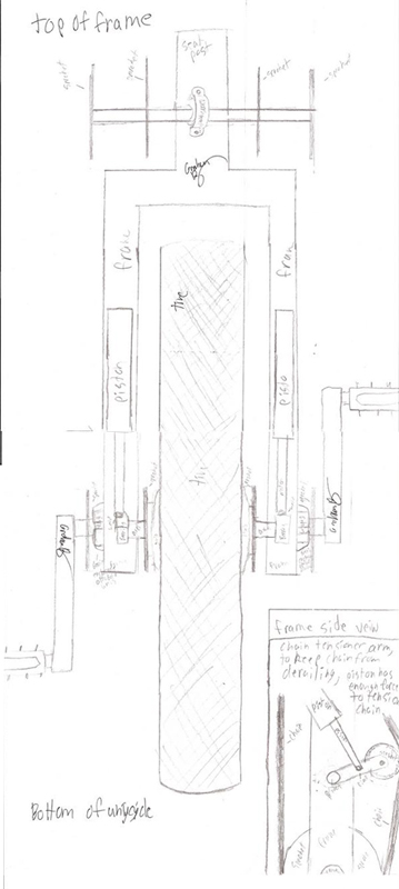
Sounds like the object here is to suspend the pedals while allowing the wheel to move up and down. But not to make a giraffe? In other words, to keep the height as minimal as possible. Lowering the pedals below the axle is an interesting idea, long as your wheel size is big enough to allow enough pedal clearance with the ground.
On the other hand, if it’s for a Trials uni, you probably need the pedals higher than the wheel axle or your clearance will disappear on big drops. Don’t forget to allow for your wheel travel and make sure there’s still room for the pedals to clear the ground, the frame to stay clear of your legs, etc.
Speaking of travel, will the seat be suspended, or is this just for out-of-seat major shocks? It’s not really “full suspension” until the wheel is isolated from the frame and pedals. That would be cool too, but sounds like a bunch more weight would be involved…
Harper’s suggestions were right-on. Your top drive shaft will need at least two bearings to hold it in place. Don’t underestimate the amount of force that will be switching from one side to the other as you pedal! If that shaft wiggles around it will foul up the system.
In general, you should consider your current drawings to be a first draft. There’s a long way to go from there to a workable prototype. Once you figure out the major engineering (like drive shaft mounting, shocks vs. springs), then step back and look at the overall thing again. Is it going to weigh 50 pounds? Maybe there’s a way to do it with less parts. As suggested earlier, you should only need one final drive chain, which will lighten things up and lower your Q-factor a bit. Your Q-factor is going to still be pretty huge though, but better to prove the concept before getting too fussy on making it fit tightly together.
Enjoy the project, and keep showing us your progress!
I think it’s awesome that you’re attempting such a cool engineering project. You’ve got a lot of obstacles to overcome, and a lot of creative input.
Regarding the naysayers. They might be right. They might be wrong, but at the end of it all, you’ll have gained some valuable experience that they didn’t.
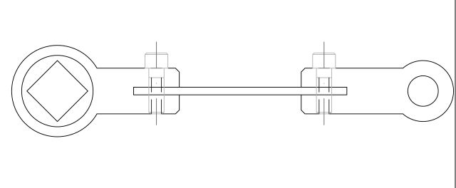
I took a minute or two to edit a set of cranks that I already had drawn. This is what it might look like.

I only edited one of them to show the comparison.
my opinion (be warned I am often wrong) the frame should not need suspention because most of the time when jumping the rider is standing up. Even with nice suspention like that I know that I would not want to be seated. Most all shocks are absorbed with the legs but hey it is a cool idea and could be the next thing for making a smoother ride on a coker on the road. For trials though I thought that the spring leaf in the crank was curious. It would maybe take out some of the shock from a big drop but may have a catapult affect on the rider after the initial bounce. Just the spring of the tire launches me off some times. I think that it would just take some getting used to but could be cool for trails. I just draw stuff but I would sure like to test this out or see it tried.
Hmm, the drawing seems to imply flexible cranks as a suspension component (I’m probably missing something here)?
but if that was taken off a large drop then in could bend, beyond its elastic properties.
I meant that only crank was flexible. Won’t that cause an issue as being asymmetric?
It just occured to me that with both the flexy cranks (awesome idea!) and the suspension wheel unicycle that there is a potential problem.
The unicycle frame, now decoupled from the wheel, has the potential to accelerate indepenently toward your crotch as you land the drop. Actually, more accurately, as you land the frame would start deccelerating faster than your crotch. You would have to ride with your seat several inches lower than usual.