Corbin V-36 (handmade 36" V-frame unicycle)

Hi All,
I’m working on a V-36 unicycle frame. The goal is to have a handlebar that won’t break; the long extension on my custom handlebar (and KH T-bars, and Nimbus bars) will eventually break. It might take a few years…but the stress of dropping it isn’t good for it.

I’d like a cro moly frame that is as light as possible. I’ve seen pictures of two KH-36 V-frames that were welded together. That will definitely work, but I want something lighter.

Here’s my journey:

Initial analysis: my choice of tubing was too small of a diameter, and the frame flexes when going up steep hills (this puts a lot of stress on it). Note, my old Nimbus frame always used to flex in this same way, and was really annoying. The KH36 frame flexes too, but not as bad. I’m moving up to 7/8" tubing to solve this issue, but that involves building a second frame. I may modify the first with double 1/2" tubing as a test to see if the concept works first.

-corbin

Corbin,

The bar extention seems to be acting as a lever working across the linear axis, so it will create a lot of torsion, esp with the lighter weight tubing.

Might it be better to bring the forward hoop closer to the main hoop, add some cross bracing as suggested by Bronson, then you could use a shorter bar extension? Also, as Didier suggested, add a brace from the rear hoop so your bar connects the two hoops.

I have two nimbus V frames, an Oregon and an Impulse, they both have somme flex, though I’m not sure it’s more of less than a single leg frame like the KH of Nimbus, but it is obvious. I do not believe that four small diameter lege are strong than two large diameter legs. Take a look at what’s going on in bike frame development, larger diameter tubes, ovalized tubes, …

The problem with making a uni frame stiff is that your are attaching your legs to a single point which is very small bearing cap that floats on a bearing, so you you need to find a way to keep the legs from twisting. Nimbus used plates, these seem to work, though they are not elegant and may be heavy.

Since you’re looking at building another frame, had you considered going with a beefed up main hoop, one that is "stand alone strong enough to resist flex, then attaching the secondary hoop to the main hoop midway between the bearing cap and the seat tube, then have a center support connecting the secondary hoo to the seat tube. This triangulation would support the handle bar without adding a lot of frame weight, and with a beefed up main hoop you would not have to worry about the frame twisting on the hub.

I’m not one for doing CAD stuff or drawing pictures digitally, but I’ll try to draw something out and take a picture, then post it. It’s a design I am considering for my own muni frame.

Yeah, definitely post your ideas!

So, the flex isn’t forward to back; the extension of the handlebar has nothing to do with the flex. It is due to the small diameter tubing. The flex is mainly right above the bearing cap. I did braze in a triangle similar to what the Nimbus frames has; this minimally reduced the flex…and simply moved the point at which it flexes to higher up (right above the triangle!). Horizontal beams across the two seem like they would create a stronger triangle, but in practice, that doesn’t seem to help, and doesn’t reduce the flex from side to side. I tested this theory by gluing on some hardwood across the two tubes to see if it helped, or if they fell off (from trying to constrain the flex). It didn’t help or fall off.

I think thicker tubing is the only solution. My temporary solution for this frame is going to be to braze another vertical seat post tube of the same diameter really close to the existing one, and see how that helps. It basically means one large tube.

But yeah, I have lots of ideas and concepts to play with. Overall, the frame feels awesome, and is super-light as-is, but will probably end up heavier if I have to beef it up a lot.

corbin

Carbon fiber? Maybe :roll_eyes:

CF would flex even more. People have made CF 36ers (one guy near me had one for a while).

corbin

I though CF was stiffer in general.

Brazing is not the appropriate solution as heat temperature makes carbon loosing and brings to poor strengh …

would tig welding it have been better?

corbin

Brazing is weaker at the weld, but this is only a problem if you are breaking the brazed weld. Brazing requires greater cleanliness of the base metals and smaller tolerance between base metals, so it’s harder to do well.

If you had a way to cast lugs, that would be very cool, esp at the bearing holders.

Are you making your own bearing holders, using cut offs, or did you buy some blanks from UDC?

Has anyone tried to design a bearing cap that is “extended” beyond the cap retention bolts? It seems to me like this would provide more stability by widening the “footprint” at the bearing.

That would depend on how much you use and how you use it. Generally speaking though, unless you only use the same volume of cf as the volume of steel you’re replacing (which is a very poor way to use cf) then you’re wrong. One option if you’re just after increased stiffness of an existing structure is to carbon wrap it - though that’s also far from an optimal solution and not one I’d suggest in this case.

I agree that larger dimeter tubes would help, and that you need the larger diameter along the axel dimension. Elliptical tubes might keep the weight down.

My impression is that you always want to build with triangles. The flex of the tube on the downward stroke would compress the inner surface of the tube and stretch the outer surface. Could you pre-tension the tubes with a small steel cable running outside the tube and affixed further out on the bearing clamps towards the cranks? A larger tubs would probably be a more practical solution, but you already have this frame built.

It looks like a great project.

Scott

Hey Corbin, I am going to have to go and visit you again just to play in your shop. Which part is flexing, the front or the rear? If only one is rubbing you could build with two different diameters.

Also have you considered adding two cross pieces that join the ‘head tube’ to the ‘seat stays’ forming a triangle that way.

Love your work

ERIC

Nice project !
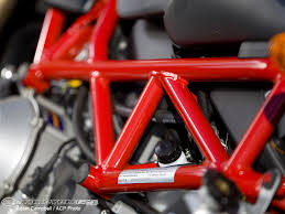
To reduce flex, why not had diagonal tubes like a Ducati frame ?

Yes for sure, TIG welding brings less temperature so has much lower impact on steel characteristics than brazing

How can that be true? Welding Chromoly requires melting it, which will not happen until you get to 1430 °C. Brazing may be slower and require longer heating, but it takes place around 800-900 °C. Both of these temperatures may be high enough to soften hardened steels, but the temperature required for welding is higher. 4130 Chromoly is supposed to stand up to brazing well. Here is a commentary:

http://www.phred.org/~josh/build/brazing.html

This analysis is only based on reported melting temperatures and is not based on practical experience. If there is some other factor that changes the outcome, please let me know.

Scott

So, may be I’m wrong :roll_eyes:

Hi yah all,
Nurse Ben – I’m using UDC bearing caps; I didn’t want to do the time to make my own, plus, why do it when you can buy them easily? I also thought about extending the bottom bearing cap location to help reduce flex. That is on my list of things todo.

Yeah Eric, come visit again!

Re brazing: it is quite easy; yes, the metals have to be very clean, but that is also easy to do. The tolerance doesn’t have to be that good, as it is simply filling in a gap with the filler metal. I never have bending or breaking at the braze or on my welds; always beyond it (usually slightly past), so the weld/braze is the strongest part.

Re flex: it is flexing side to side; the wheel rubs on the frame tubes under the seat. The flex is right past any support I give the main tube (i.e.: a brace, or triangle), and I think it can only be remedied by larger tubing, or a double up of tubing.

corbin

Maybe try I-beams instead of tubing? I think I recall someone doing that for a V frame a while back.

That would be heavy! The circle/oval shape is superior in strength for a given amount of weight. (otherwise, we would see all bike frames made of i beams!).

Definitely keep the ideas flowing.

Part of the problem is that a lot of these ideas may not pan out. There are two ways to find out if they work:

  1. A 3D CAD model that can simulate bending amounts with a given material.
  2. Make it and see.

I, unfortunately, don’t have a CAD program that can do #1, so my only option is #2.

corbin

But you do have a friend who can get you into a shop with such computers available… :wink: