The problem is ensuring that both hubs have the same gearing. If they are very slightly different, then pedalling in one direction will result in lockup. The cranks drive the hub, the hub drives the wheel, the wheel drives the other hub, the other hub drives the cranks - if the hub driving the wheel has higher gearing, then the hub driving the cranks will attempt to turn them faster than they’re going (remember that the reverse direction hub is acting in a similar way to what happens when pushing a bike backwards - it makes the cranks turn, with the freewheel only kicking in if the cranks are turning faster than the hub wants to turn them).
Would it be more feasible with one of the other internal hubs such as rolhoff speed hub.
Although 1 speed hub on a uni would be heavy and expensive, 2 would be crazy,
But for 11 gears and 300% variation, might be interesting
This was actually my initial plan for the project. To prevent lockup when rolling forwards you would just have to preset the hub transmitting forwards torque to always have a slightly lower gear ratio than the hub doing reverse torque. The main downside to this approach with two Nuvinci’s is that it would be huge and heavy.
With a pair of lighter and smaller indexed hubs it might be feasible though. To prevent lock-ups during the gear transition in this case you’d probably need to stagger the shifting. So on up-ship you would change the reverse torque hub first and then the forwards torque hub 2nd, while on down-shifting it would be the opposite sequence. I’m sure with some clever tinkering you could do this with a single shift mechanism which would be slick.
-Justin
I know this must have come up before, but can you modify a single hub to take reverse torque? I understand why is does not work with the nuvinci hubs (they are pre-loaded in one direction only) but I do not really understand the design of the other shifting hubs.
Scott
2014 Project Update, shifters
Well, in the last 2 years this project hasn’t sat totally idle, I converted it back to a 3 speed drive instead of the Nuvinci CVT for Unicon16 in Italy, and then restored it to have have the Nuvinci along with shifters and a hub motor for the San Mateo maker faire in 2013. And then did a few more upgrades in time for Unicon17 last week where it got to finally see some good action!
One of the big problems facing the original build was this:
The Nuvinci hub I used in this project was from their now discontinued N171 developer kit
http://www.nuvinci.com/09_lev_kit.asp
which included a stepper motor drive electronic shifter that I was planning to use, but whole shifting assembly was massive and ugly and as a result was not installed.
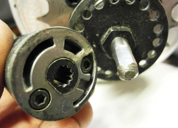
I was going to then use the standard handlebar twist shifter instead, but realized that the shaft on the N171 from the developer kit is a share, while the shaft for the regular N171 nuvinci hub with manual shifting is a splined star shape.
It turns out it is more than just the shaft interface that is different, the electronic shifter shaft has a much finer pitch lead screw than the manual shifter, meaning that it takes twice as many turns in order to fully shift from low to high gear. This was probably done to reduce the motor torque needed for the electric shifting.
If the handlebar shifter was used on the developer kit N171 it would only be able to move through half the total gear range. Normally that wouldn’t be desirable, but in my case I can only use the bottom half (from 0.5:1 to 1:1 ratio) of the Nuvinci’s range. If the gear is shifted past the 1:1 ratio, then the wheel locks up in the forwards direction which isn’t good.
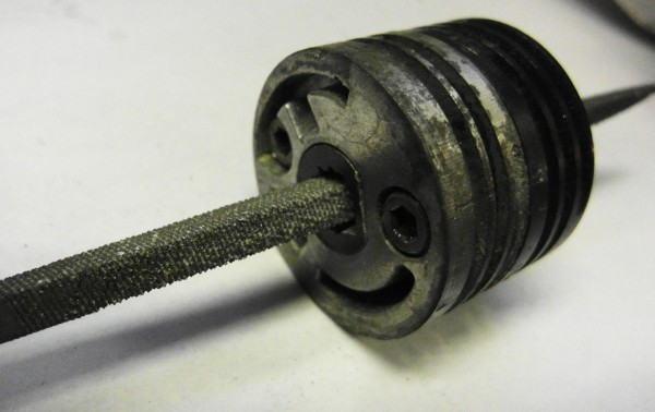
So, by filing the mechanical shifter cable drum to fit over the square shaft, I ended up not only getting the desired handlebar shifting, but did so in a way that also intrinsically prevents the user from ever being able to shift beyond the 1:1 point and crashing.
I added a couple of steel tubes as a bash guard so that the shifting mechanism is protected in the event of a crash and so far it has been working perfectly.
Electric Hub Design
The original build had a simple freewheeling hub made from a 20mm thru axle front bike hub with a square taper axle going through it (see posts# 20-23).
One of the things I was really curious about is the concept of using a motor to generate the reverse torque rather than using a mechanical transmission for it. So much complication with the variable speed geared unicycle is the requirement for a bidirectional torque transmission, since all the internal bike hubs are unidirectional and freewheel in reverse.
In principle, you could have a torque sensor that detects when the rider is attempting to put backwards pressure on the cranks and immediately have the motor engage in a regenerative braking mode, which would cause the rider to then resume forwards pressure on the cranks to stay balanced. If it’s possible in this way to use the motor so that the rider is always modulating and maintaining forwards pressure on the cranks, then that would open up the possibility of using any hub gear or even derailleur gears for a multi-speed unicycle.
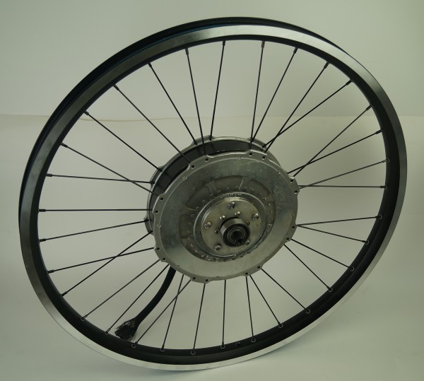
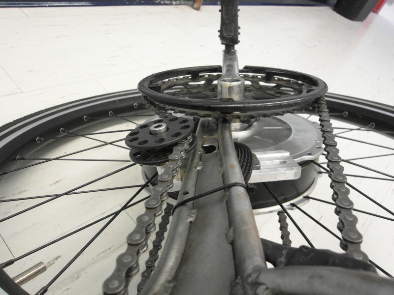
So, the simple hub was replaced with a hub motor design not unlike a much earlier build described here:
Only this time, the spindle stayed completely decoupled from the motor rotor, so that they could be linked via the external chaindrive transmission.
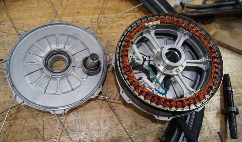
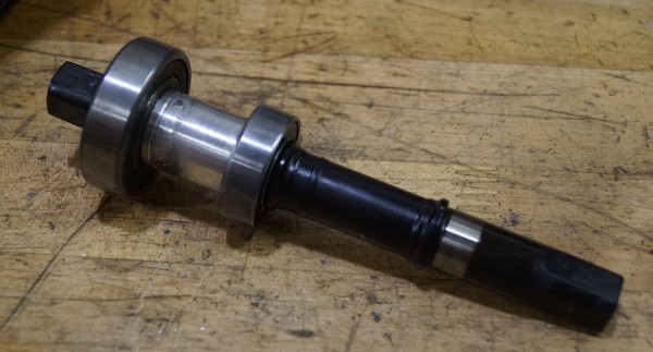
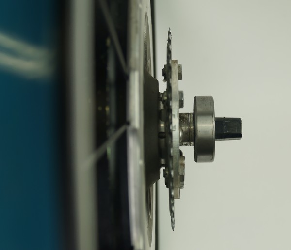
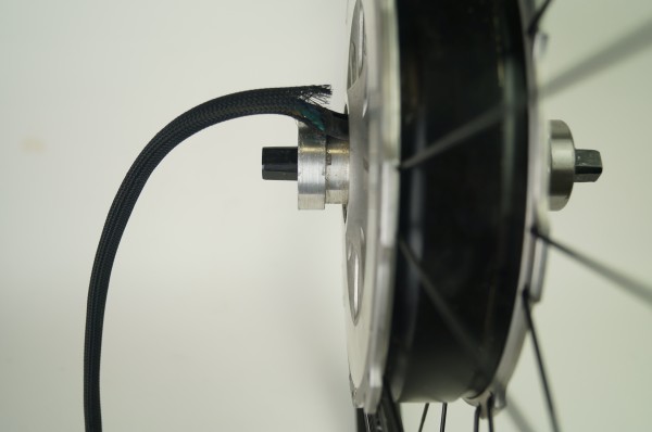
Here are a few additional pictures of the motorized wheel. The left side had a fixed non-rotating 42mm shaft which is coupled to the motor stator and has the motor wires coming out, while the right side has a 30t chain sprocket bolted to the disk holes on the motor cover plate. The right side axle is on a standard unicycle bearing. The square taper spindle itself came from taking apart an extra long (156mm) bicycle bottom bracket.
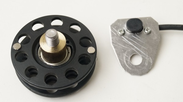
Idler with Cadence and Torque Sensing
Another thing I learned from these chain drive experiments is the need for a chain tensioner and idler in order to prevent the chain from popping off when the unicycle is under significant stress. In this build though, the idler serves several other purposes too. Two magnets are fit in the housing and wired up a bicycle cadence sensor so that the speed of the chain travel and hence the rider’s pedal cadence can be accurately measured. With the 10t idler and a 48T chainring on the right, there are exactly 9.6 magnetic pulses per pedal revolution
The aluminum mount for the idler can slide back and forth to set the chain tension, and it also has strain gauges glued on the top and bottom surfaces which enables it to measure the chain tension and hence the rider’s pedal torque. With both the torque and cadence, we can record the actual human watts output of the rider. Unfortunately this ended up getting permanently bent at one point in unicon which caused the strain sensors to be saturated, so I wasn’t able to measure and make use of rider’s pedal torque this time around.
This is such a fantastic project! Congratulations on such a successful implementation and all your hard work! I saw your objet d’art at Unicon but hesitated to try it since I tend to be crashy. Have you considered a freewheel version? There are a few of us out there putting decent mileage on such unicycles.
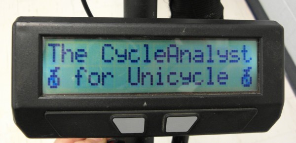
Cycle Analyst
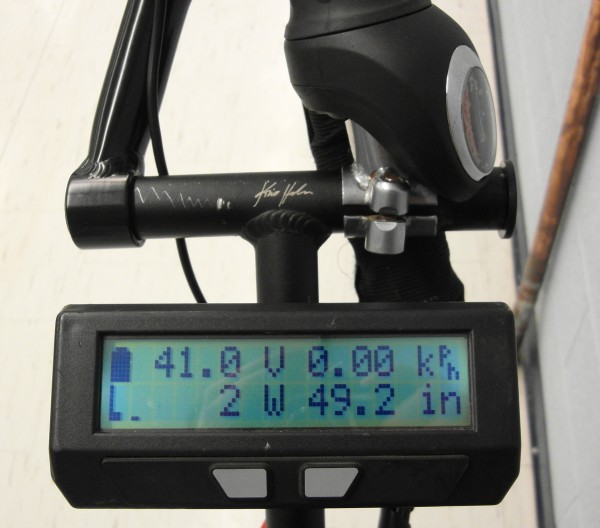
For the control interface and display, I’ve been working on a custom firmware build for the Cycle Analyst specifically for this project. One of the fun features is that since the Cycle Analyst knows both the riders pedal cadence from the idler magnet, and the wheel speed from the motor hall sensors, it is able to compute and show in real time the equivalent gear inches of the wheel as you shift the nuvinci up and down. So you can see that in the bottom right hand field where it shows 49 inches. Geared all the way up it would be at 64-65", while geared down it would read about 35".
This is useful with the continuous transmission hub since otherwise there is no easy way to be sure just what gearing you are in. There is some visual cue from the nuvinci grip shifter, but it’s pretty qualitative.
Oh really, what kind of distances? and I presume you are feathering the brake at all times? I heard that there was a freewheeling muni that was around at the downhill event but I didn’t get a chance to see or test it. ![]()
As to your question, yes a freewheeling version would be much easier to build, and it would be pretty trivial to remove the one way clutch in this current project and allow the nuvinci hub to freewheel. Then the wheel wouldn’t lock rotating backwards and it would also enable the full 360% gear range of the hub, meaning rather than topping out at ~64 inches it could go right up to like 110inch wheel size. But I wanted to do this only after sorting out automatic electronic braking via the motor, as discussed in this post.
OK wow, just had a look through of our discussion thread and videos on this topic and I am thoroughly impressed. As someone who can’t even glide let alone coast any distance, I wouldn’t be the best test subject for this but I’d sure be happy to see someone give it a go.
It would be quite trivial for me to revive the old 3-speed S3X project and replace the S3X hub with like a Shimano alphine 11 or similar. Then you’d have a fairly lightweight freewheeling unicycle with a pretty crazy 400% overall gear range. And since backlash isn’t a concern at all, we could use much smaller diameter sprockets going up and down to the transmission hub which would keep the look clean too.
If you can pull this off and ride long duration with confidence on a freewheeling unicycle then I dare say you could be up for a huge advantage at any of the distance events at the next Unicon!![]()
LOL @ 60mph waaalrus! Your trike hub could be obsolete before you even build it. 
Since January I’ve put in nearly 1070 freewheel miles, mostly on trails. My latest focus has been pump tracks but I’ve also recently starting doing road rides in the neighborhood of 20 miles at 8mph on a 26" wheel and I want to work to push that up to 10-12mph. I’m not comfortable going faster than I can run out, particulary when I’m coasting. On non bumpy ground my rhythm is pedal fast for a short time then coast until my speed decreases sufficiently then repeat. I use the break to reduce my speed on descents and occasionally as a balance adjustment (particularly if I’m tired or a car is passing me). I use the brake a lot more on bumpy trails. I still have considerably more UPDs than fixed wheel unicyclists which reduces my average speed. I’m also no physical paragon so the Unicon distance records are safe. I do believe the freewheel will provide an advantage given enough practice; it’s just that advantage is over my own fixed wheel riding which is inconsiderable. A different rider would have a greater advantage. I expect to get experience this year riding a 20" single speed 3.8x geared freewheel unicycle as mentioned in this thread and I would love to give your old 3-speed project a spin with the freewheel modification at some point if it could be arranged somehow.
Coming from someone who felt like they were close to taming the beast. This thing was really awesome and I wish I could have taken it home with me. 
I can wait to see what crazy awesome modification you manage to come up with in the next two years! I dont know how I would feel about a Freewheeling version of this going at speed more than double of what i was doing…
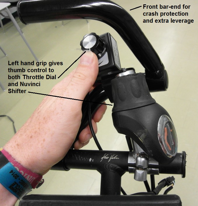
Handlebar Gadgets
With so much going on, it was a bit tricky to figure out the best way to control all these things while riding and after some jigging around with the handlebars and bar-ends at Unicon this is what we came up with.
For me, as somebody who rides with my left hand on the seat or bars and with my right arm outstretched for stability, it worked perfect, since I could use my thumb to roll the throttle and the shifter all while maintaining a tight grip on the bar. For people used to holding with the right hand it wasn’t quite as ideal, and some like Martin opted to hold the seat bumper with one hand and then use the other hand on the controls.
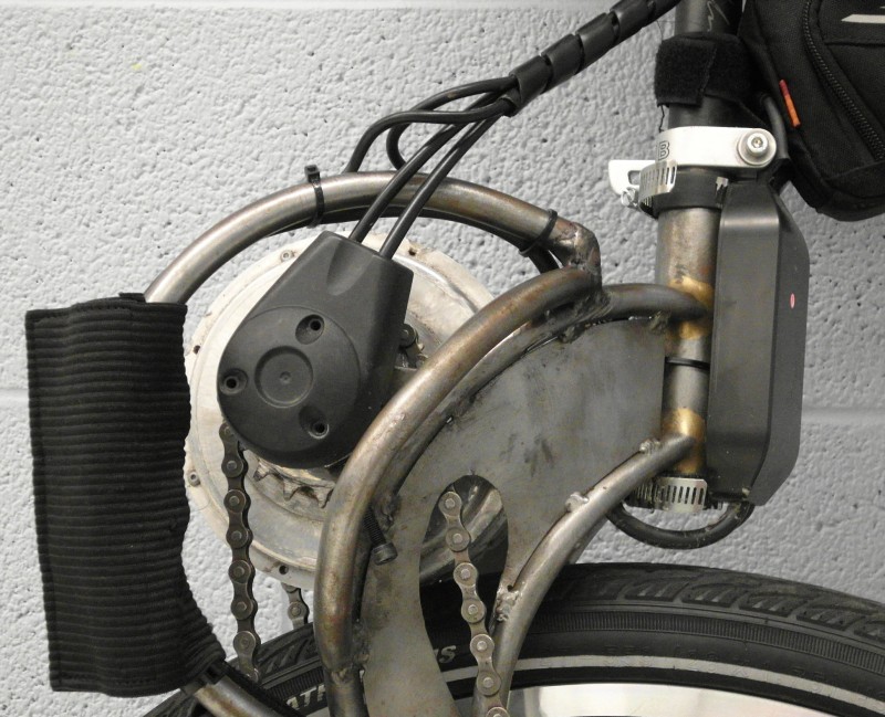
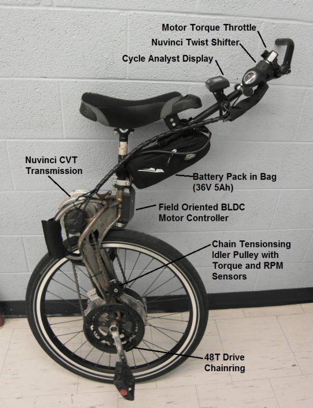
Finished Build Project
Here is a side view of the end result showing the various components that make up the drive. I haven’t talked too much about the electronics here, but in the implementation that was running at Unicon it was setup as a manual torque control device. So the throttle dial on the handlebars sends a signal that directly controls the motor torque via the field-oriented motor controller.
At mid-point, the motor is producing no torque, turn the dial clockwise and it produces a forwards driving torque, and turn it counter clockwise to get a regenerative braking torque. There is no return spring on the throttle dial, so it just stays at whatever value you turn it at. This is nice when you are riding, but it does mean that if you bail with the motor on then the wheel keeps in spinning since I didn’t have any kind of kill switch setup.
Hi Bobby, it was awesome to have you and all the others brave enough to not only take it for a test rides but really figure it out and put it through the paces. So thank you Bobby, Martin, Dave Cox, Thierry, and all the others who had a go and were able to provide useful feedback. The learning curve was not easy, but a handful of people used to geared cokers were able to freemount and ride (somewhat nervously) after just a few tries.
Wow!
Great developments on an already amazing project. Wow
Wow, so you managed to get it riding at the circuit. Have you recorded any lap times?
And that uni looks like it came from the outer space