> Ken Cline wrote:
> > *
> > … Second, work dont on the damper would be wasted
> > energy.
>
> This arguement is used against using suspension in mountain biking but I
> know from my own experience and from the racing world that overall it
> saves energy.
I didn’t make that argument about suspension bikes.
I think there is a critical difference in the case of the suspension
wheel. Here, the dampening would be placed inside the wheel. Every
revolution you pedal, you’d be fighting to compress the dampeners that
are engaged sequentially are the wheel goes around. All of that
energy is wasted. Remember, the dampening action is against the
rider’s complete weight plus dynamic pedalling force. On a bicycle,
you’re only fighting the dynamic component of pedalling force.
Anyway, the fact that dampening will make the wheel tend to ride
eccentrically after a compression event is an even more worrisome
concern to me. Any Dampening must be light enough to allow a
significantly higher frequency than the maximum pedalling cadence.
I already had an idea of doing what Cyberbellum did. Good idea putting the spokes on the outside of the suspension. But I still like my parallelogram design which would eliminate windup, while his would only minimize it. Putting them at a tanget to the hub is a good idea though, if that design were to be used.
John, I will think about putting the wheel on a seperate suspension from the pedals.
Ooohhhh! That suspension wheel is becoming really great!
Those are all nice ideas, but you should also think in 3D when you’re designing. I do like your parallelogram-stifening bars-, maybe it could be like a 4 bars structure to avoid side-to-side twisting (brake rubbing). My 2 cents.
Keep on the good engeneering!
Vincent
-Edit: Forget about the brake, it should clearly be a disc brake specific machine.
I do believe the only flaw in my last design is lateral forces like you mentioned. It would not be strong if you were to push it sideways, or push down on one side harder than the other. This is a serious problem though.
I don’t think it would completely, there would be a little bit of slack in either direction when you pressed down on the pedals. They would wind up until they were touching, at which point they would begin to transmit the forces to the rim.
Whilst they were not touching, they would just act like two shocks would, and wind up until they were touching.
Depending on how much play there was, this could actualy be slightly harder to ride than a wheel where the shocks wind up, because there would be no resistance to the rotation of the pedals. If the parallelogram was dampened, then it might be less noticable, or if the two sides were as close as possible together, but that would mean it couldn’t move very far before we had the same problem as with the earlier design with the telescopic pole.
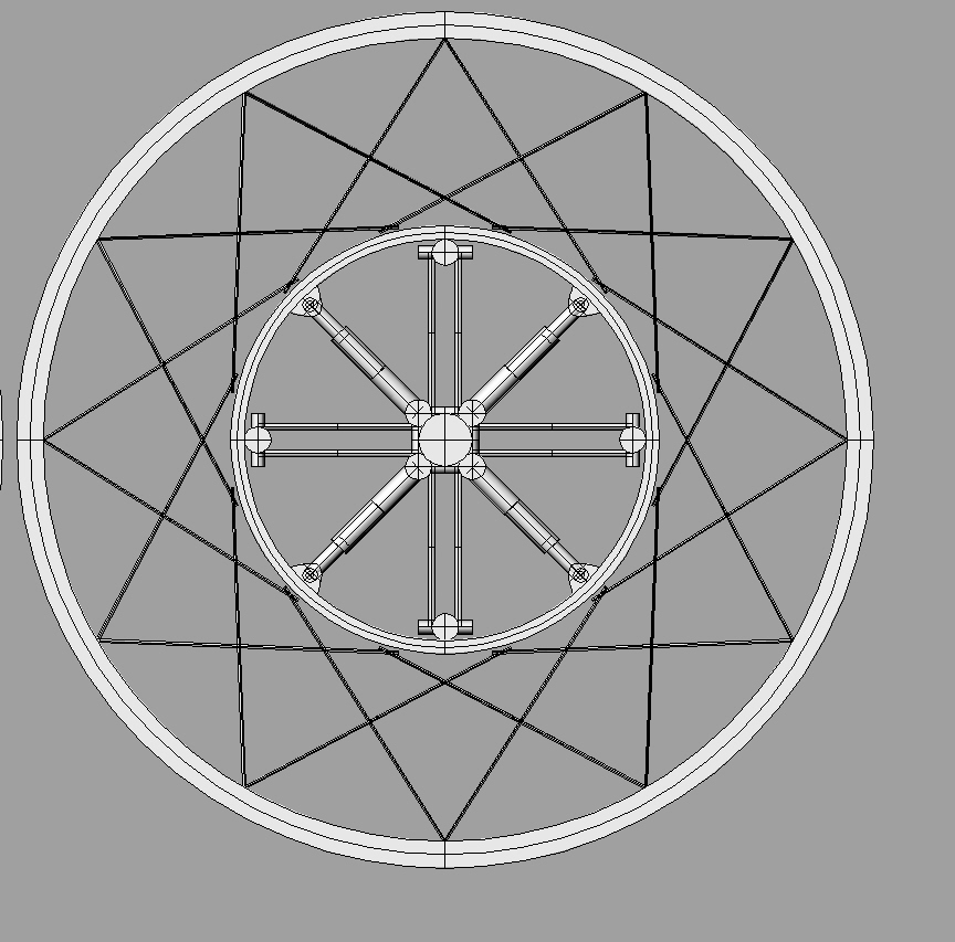
I’m a bit confused about how the Rayden’s design works.
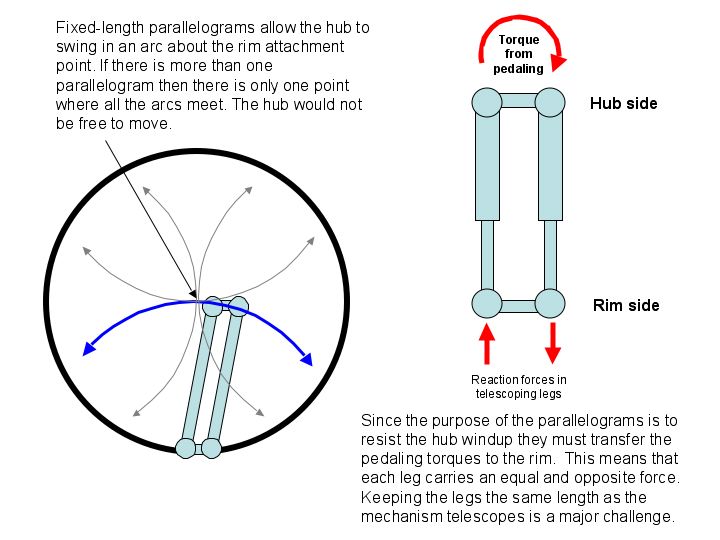
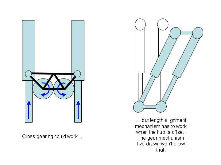
It looks like the corners of each parallelogram are hinged to allow the mechanism to deform from strictly rectangular to any parallelogram. If the rim side of the parallelogram is the fixed reference point then the hub side can swing in an arc but must stay parallel to the rim side. The idea is that staying parallel is the same thing as preventing windup. Have I got this part right?
If this is correct, then each parallelogram allows the hub to move only in an arc centered on its rim side. Since there are four mechanisms there are four arcs, and since each arc swings on a different path there is only one place the hub can be. Each mechanism would effectively be a stiff pair of spokes and the hub would be locked into place as if it were part of a conventional wheel. Rayden, clearly this isn’t what you have in mind.
You describe the spoke legs of the parallelograms as telescopic, but if they telescope independently then there is no reason why the hub and rim sides of the parallelogram should stay parallel. What’s missing is a method for keeping the telescopic legs equal in length as the parallelogram expands and contracts.
This won’t be easy to do because the telescopic legs must carry the pedaling forces. I’ve got to make another picture of this so I’ll continue in a following post.
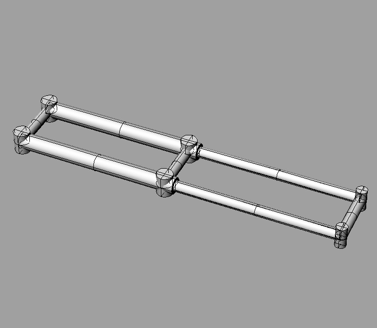
I see what you mean. I’m having a bit of trouble visualizing how to prevent this. I drew this up and it might fix it, might not. I will include another picture showing why it would prevent the hub from spinning independantly.
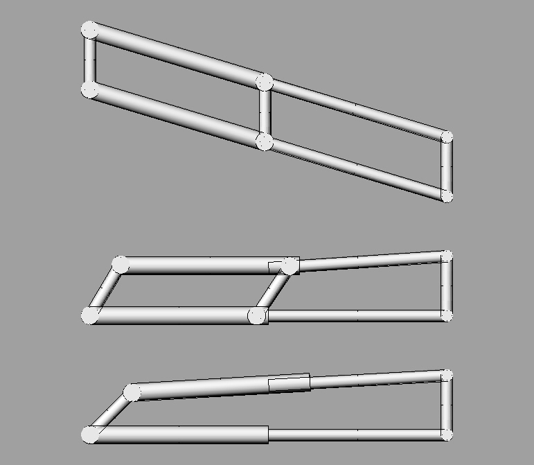
The first image is how it should rotate. The third is how it would rotate without the extra piece. The 2nd is showing why the piece prevents one side from rotating without the other.
And yes whoever asked about the parallelogram telescoping, it does, i just didn’t draw that up in my models. This model of the parallelogram has it.
I like a lot of these ideas, but I’m curious as to why we want a suspension muni in the first place. A good muni right now already costs at least $400, and a greazt one runs about twice that. And none of these are suspended. Not to mention, most of them weigh a hefty 15-17lbs. The added suspension would add about 2 lbs at least, and at least another $200. Have you ever been in a situation where the squish of the tire was inadaquate? If you truly need suspension for your riding, the solution is not to build a suspension muni, but to lower your seat and practice. It’s cheaper, easier, and more effective than building a suspension muni.
Gerblefranklin, you make a lot of good points. In another couple of pages I’ll elaborate on them. In answer to your specific question, it isn’t a matter of need. It’s the challenge. Mountaineers climb mountains “because they are there;” engineers design things “because they are not there.”
Reminds me of this joke:
"There are three kinds of people in the world. Some people see a crooked picture and ignore it. Others can’t stand imperfection and fuss with it until it hangs straight. Engineers think, “this frame needs a solar-powered device with sensors and actuators to straighten it after it gets bumped.”
Think of the mtb evolution. First there were no-suspension mountain bikes. Then came the front suspension, people started to ride down hills, and later the double suspensions appeared. Now biker do gap of 40 feet on their full 12’’ of travel machines.
Muni is still young and in full evolution. We are used to ride the ‘‘hard-tail’’ munis, but maybe fully suspended unicycles would develop another type of riding (more terrains rideable), or just make the super technical trails more comfortable.
As for the weight and cost of the product, it doesn’t matter to me: these will probably lower since there will be more and more of suspended munis.
P.S.: And YES I’ve been in a situation where the ‘‘squish’’ of the tire was not enought.
cyberbellum, you said the parallelogram would jam, but I am assuming that it would be built well enough so that instead of jamming it would transmit the force. Seems like it would work to me…
The middle diagram in your last sketch shows the upper telescopic leg bent, with the interior part jammed in the exterior part. Hence my assumption.
The middle diagram also shows the left end and the right end out of parallel. Since this is the effect you are trying to achieve it seems that the design isn’t all that effective.
The short version is that, even though from a pure math perspective it seems promising, from an engineering perspective it would be impossible to make parts stiff enough to do what you want. The problem is with the basic geometry of the solution. Even a mechanism built like an engine block would allow some angular play in the rim element. I could go on and explain why, but that would require a page or two of math and solid mechanics and I don’t have that kind of time or energy.
The midday heat is over here in DC so I’m about to follow gerblefranklin’s advice and go out for a ride. Yesterday I went a couple of miles on my 29"er with only one UPD (if you don’t count the dozen or so UPDs just trying to get started). Today I think I’ll work on my freemount with the 20" unicycle. I still haven’t managed better than a 10% success rate. I know I can do it - the 20" is such a toy - but I’ve got some sort of mental block going.
Rayden, I owe you an explanation. This is the best I can do without going into the mathematics of the problem. Not sure what your background is but you seem pretty clever so I think this might be enough explanation. PM me if you want me to go into the details.
Thank you for the compliment. My background in things mechanical is limited. I am a freshman at a jr college, might be transferring in the fall to do computer science. My second choice would be ME I think.
I understand what you are saying. Let the blue half be attached to the rim and the green half attached to the hub. Would the problems you describe happen? I don’t think they would. If the position were reversed then it would be a serious problem. But by rotating the far left vertical green piece I am not sure you would have problems.
Please criticize my diagrams, ideas, or assumptions as much as you would like. It is only because of criticism that I have come up with many of my ideas.
It’s a symmetric problem so it doesn’t matter which part is attached to the hub.
Ok, I’ll try it again:
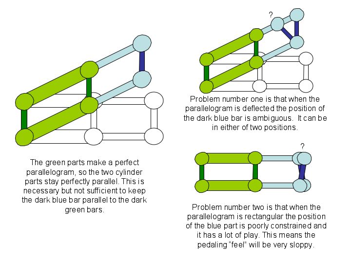
What happens when you keep the parallelogram level but rotate the far left green part? The two horizontal cylinders stay parallel but come closer together. When they come together either the light blue bars bend or the dark blue bar rotates. Assuming the slides are frictionless, how does the dark blue bar know which way to rotate? And if it guesses wrong, how can it get back to the right position?
Assume the dark green bars are held perfectly vertical, and the horizontal blue bars are held perfectly horizontal. The cylinders are parallel and as far apart as they can get. What keeps the right hand blue bar vertical? The fact that the two hinges are at their farthest distance apart, right? Now assume that the light blue bars are made out of real stuff; that is, they deflect a bit when a force is applied. Mentally grab onto the dark blue bar and give it a twist. What happens? The ends barely move up and down, right? But they move in and out a lot. Remember your trig class? What is the right bar doing? It’s the hypotenuse of a right triangle with a very small angle. What’s the tangent of a very small angle? Very close to zero. It’s also the ratio of vertical deflection of the hinge to the horizontal deflection. In other words, the hinges on the blue bar can move pretty far before they make a significant bend in the elastic light blue bars.
I gave you a couple of good hints as to how this problem can be solved a few posts back. Why don’t you make a simple experiement by sliding some rulers and quarters around on a table and see if you can solve it?