The question is how to accelerate to the speed of light without evaporating in the first place. CERN could have some ideas on this matter.
Nope but good guess. I do like the sleeping sloth though.
I work in a german particle accelerator facility. During commissioning of the longest accelerator I used to ride my g36 in the straight 3.4km long accelerator tunnel where others rode a bicycle. Somehow that didn’t help me to get close to the speed of light.
4 Likes

At least you tried.
Hey yall! I think I made a discovery!@Justin_LE check this out! This might be a new spin on your old nuvinci build

Oh wait, I think I see the issue here, that’s exactly what Justin did and why it didn’t work, the concept is there but it needs some help.
In my mermory is right, the ratio is different between forward and backward
1 Like
By looking at it the ratio appears to be the same but due to shenanigans with Justin h had to change the ratio which caused it to have a higher gear (63G”) going backwards without the CVT
How far I am on this subject:
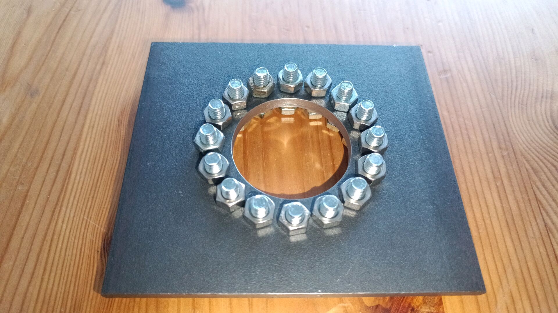
Thanks to @UniGeezer it took 5 minutes to put the hub loosely into a wheel, this was obviously on 03.06.25 and shows my slow progress until now.
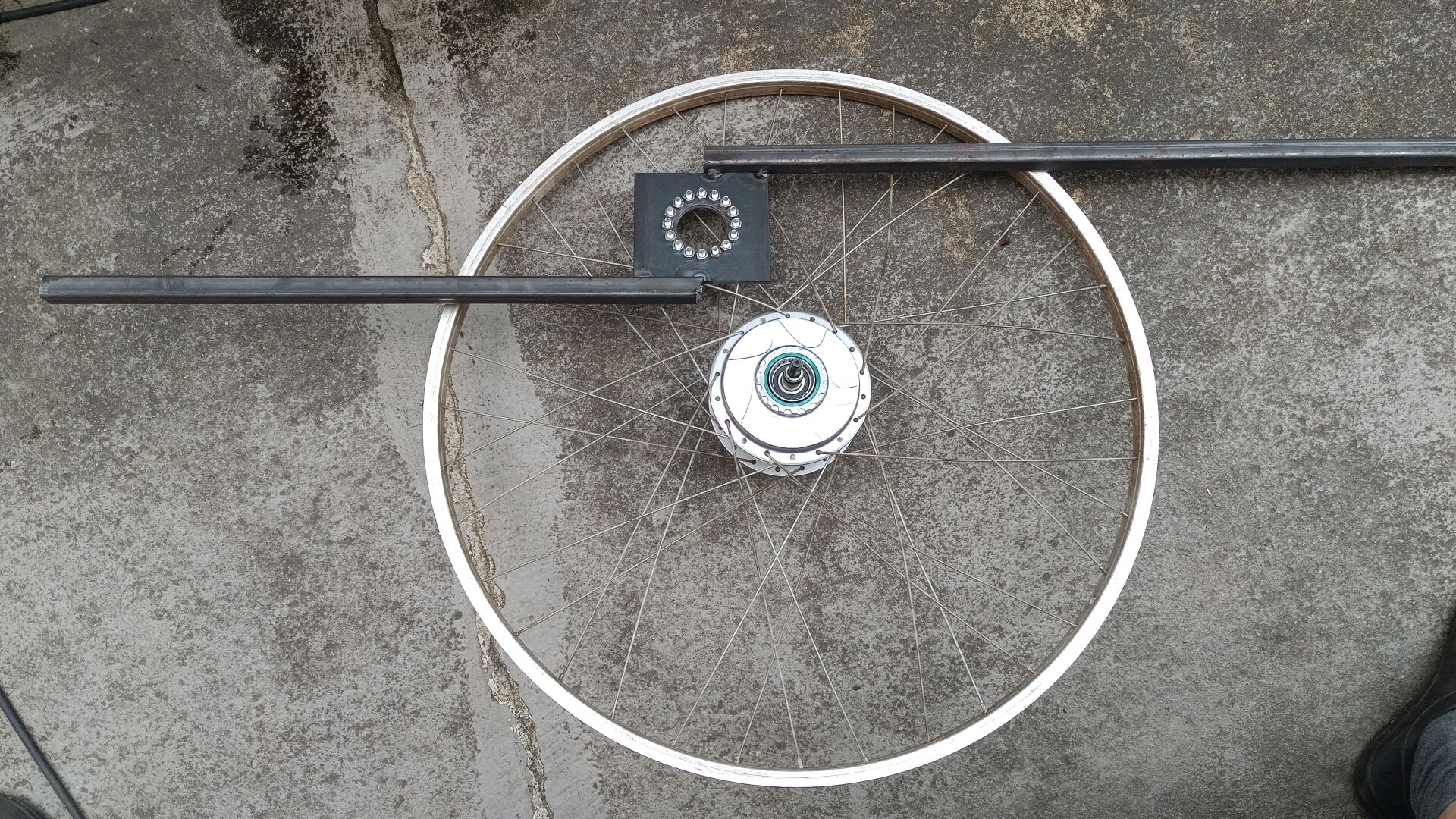
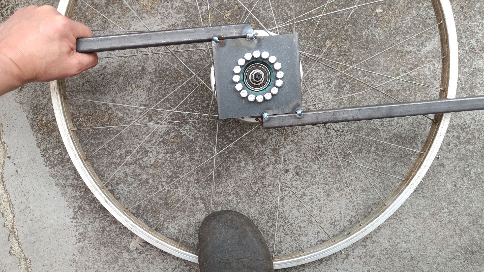
The freewheel clutch is a solvable first problem:
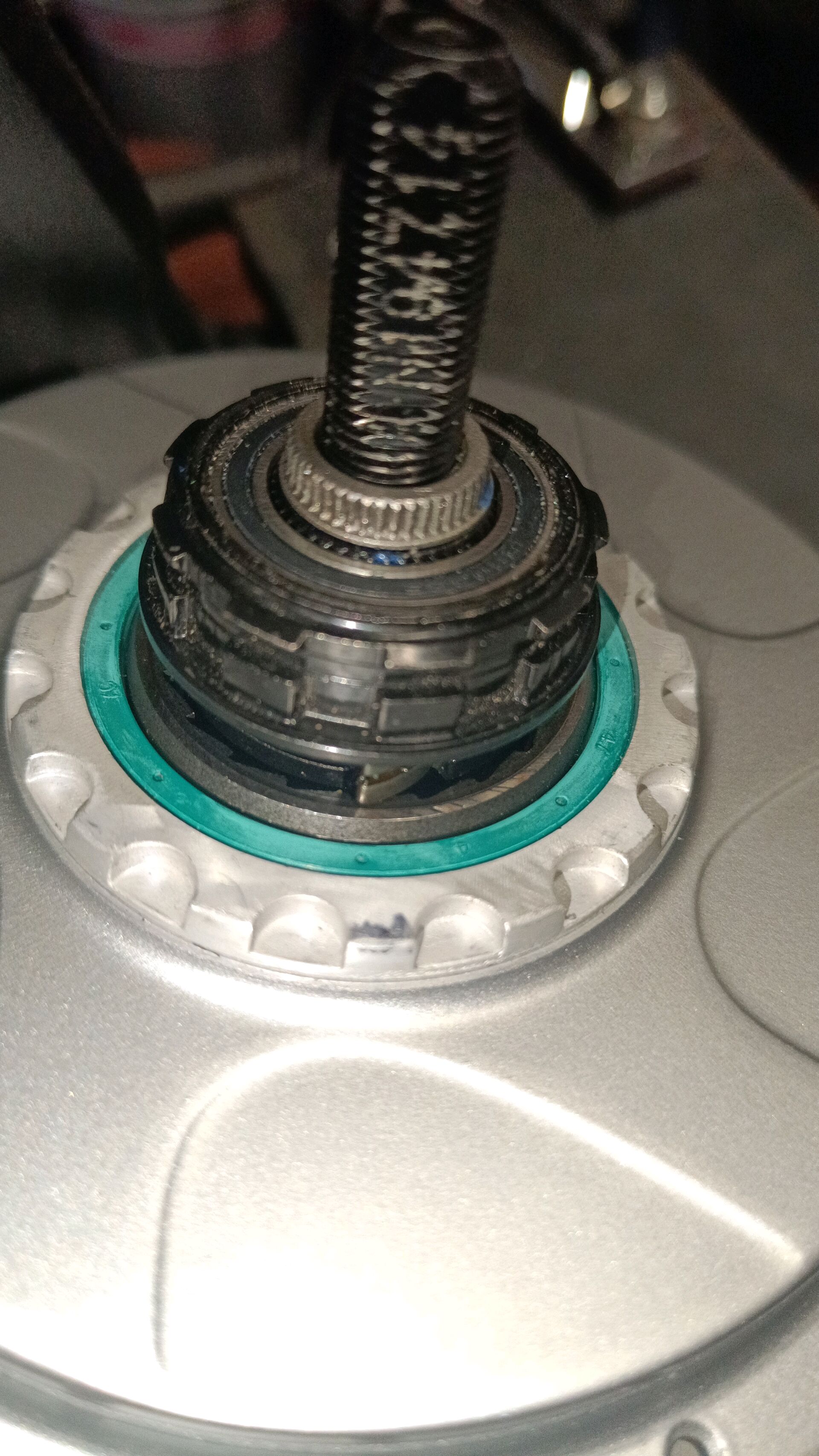
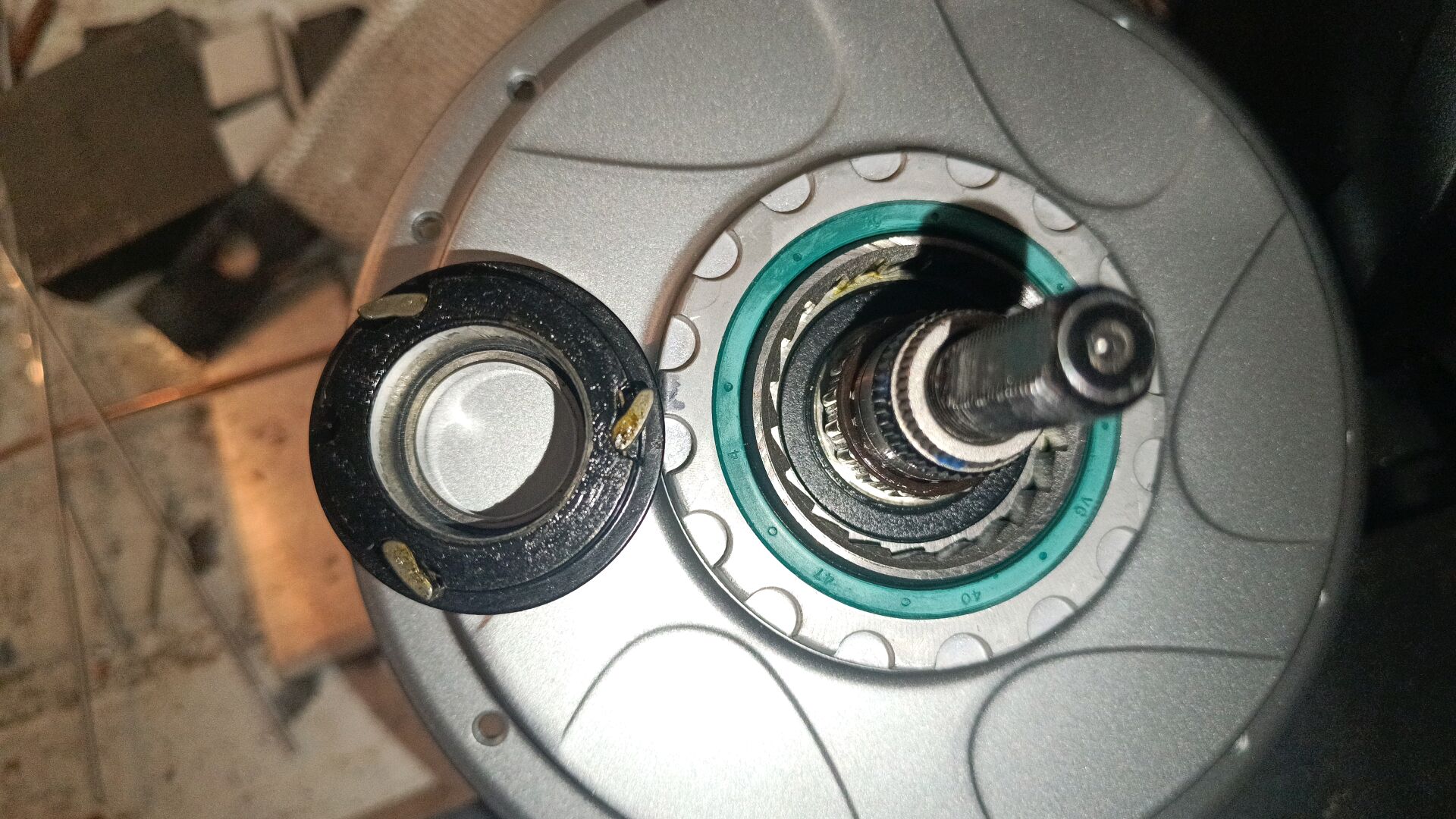
Welding would certainly destroy the sealing O-ring and hardened stuff is usually not weldable. Re-machining the clutch section is feasible, i.e. with a flange to mount conventional sprockets:
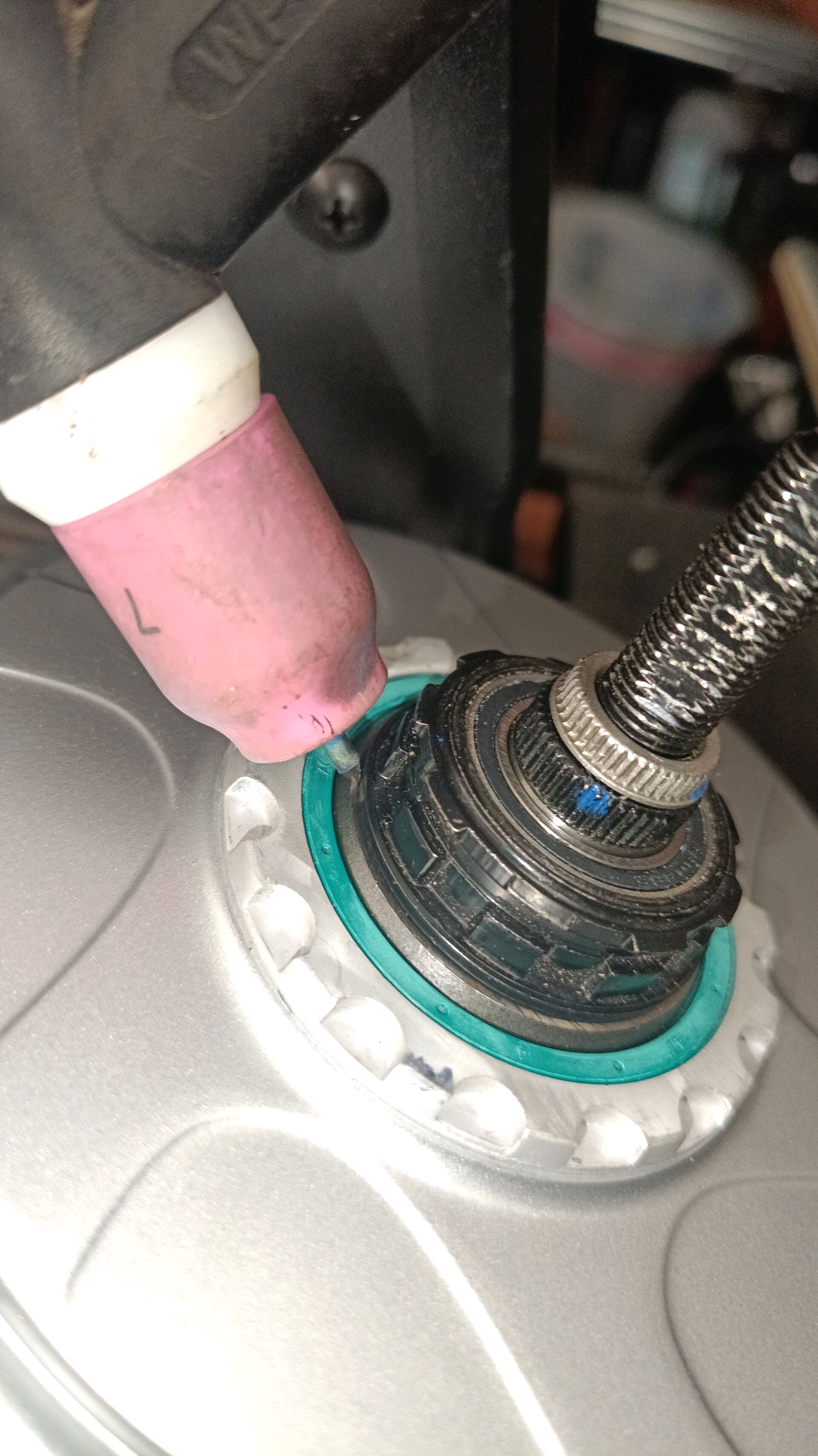
The 2 problems are shown on the next picture:
a) the freewheel clutch (in the center)- can be welded or machined
b) 2 of the 4 asymmetric and distinct (height and backside groove) CVT ball clamping rings- they have to be machined to be symmetric.
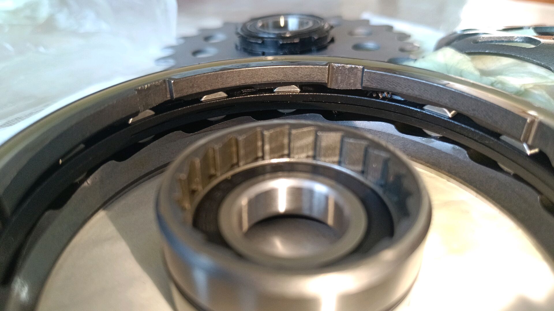
It was disappointing to see that the 4 rings are not equal, what just takes longer time.
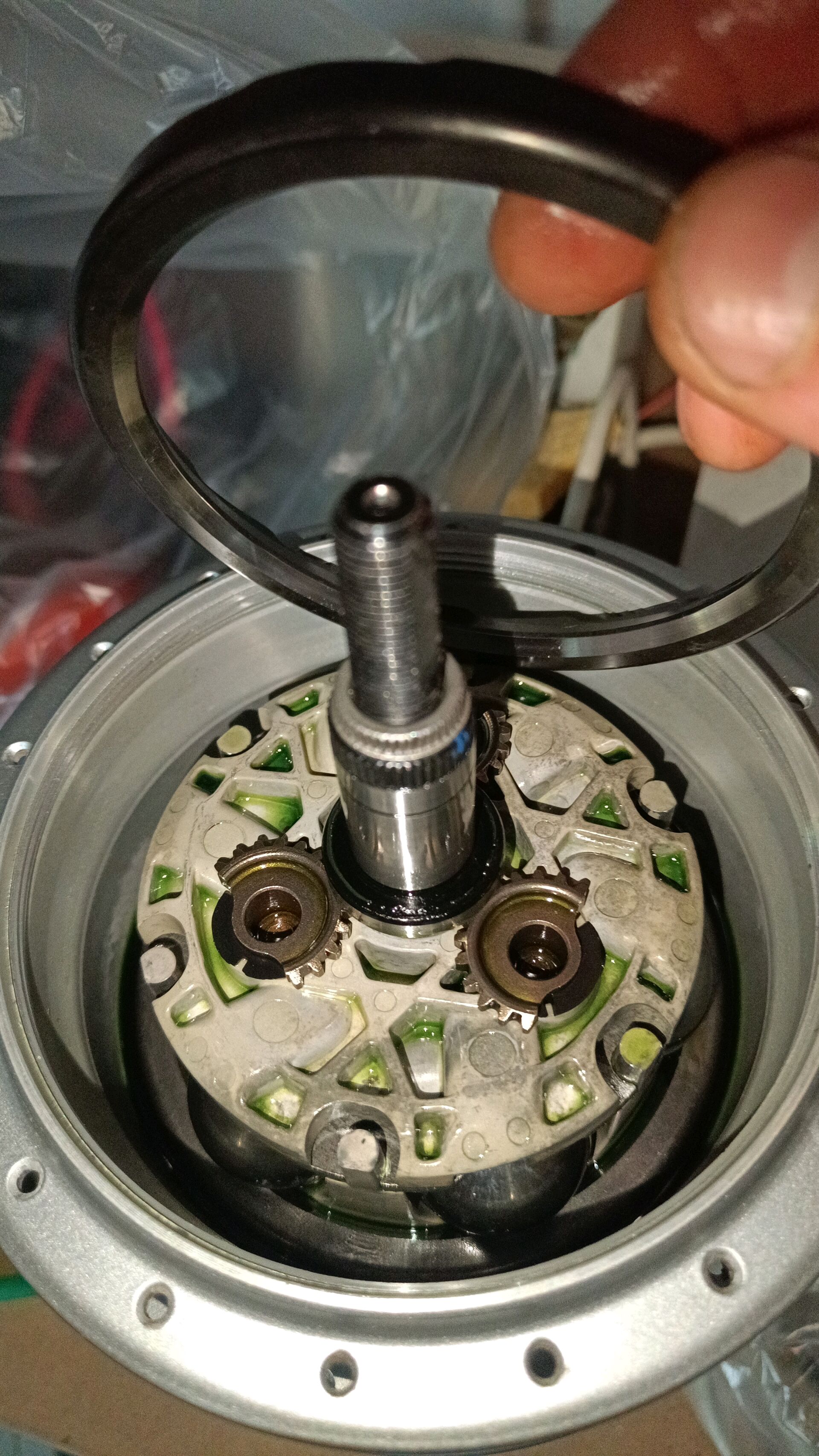
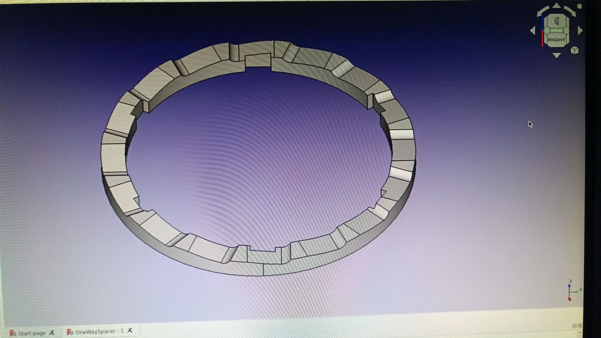
Drawing of the asymmetrical original:
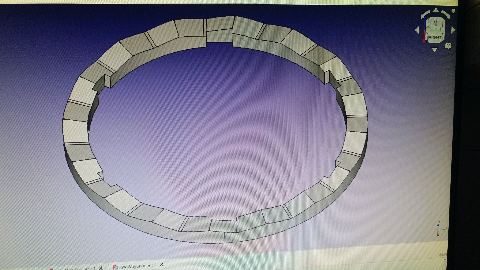
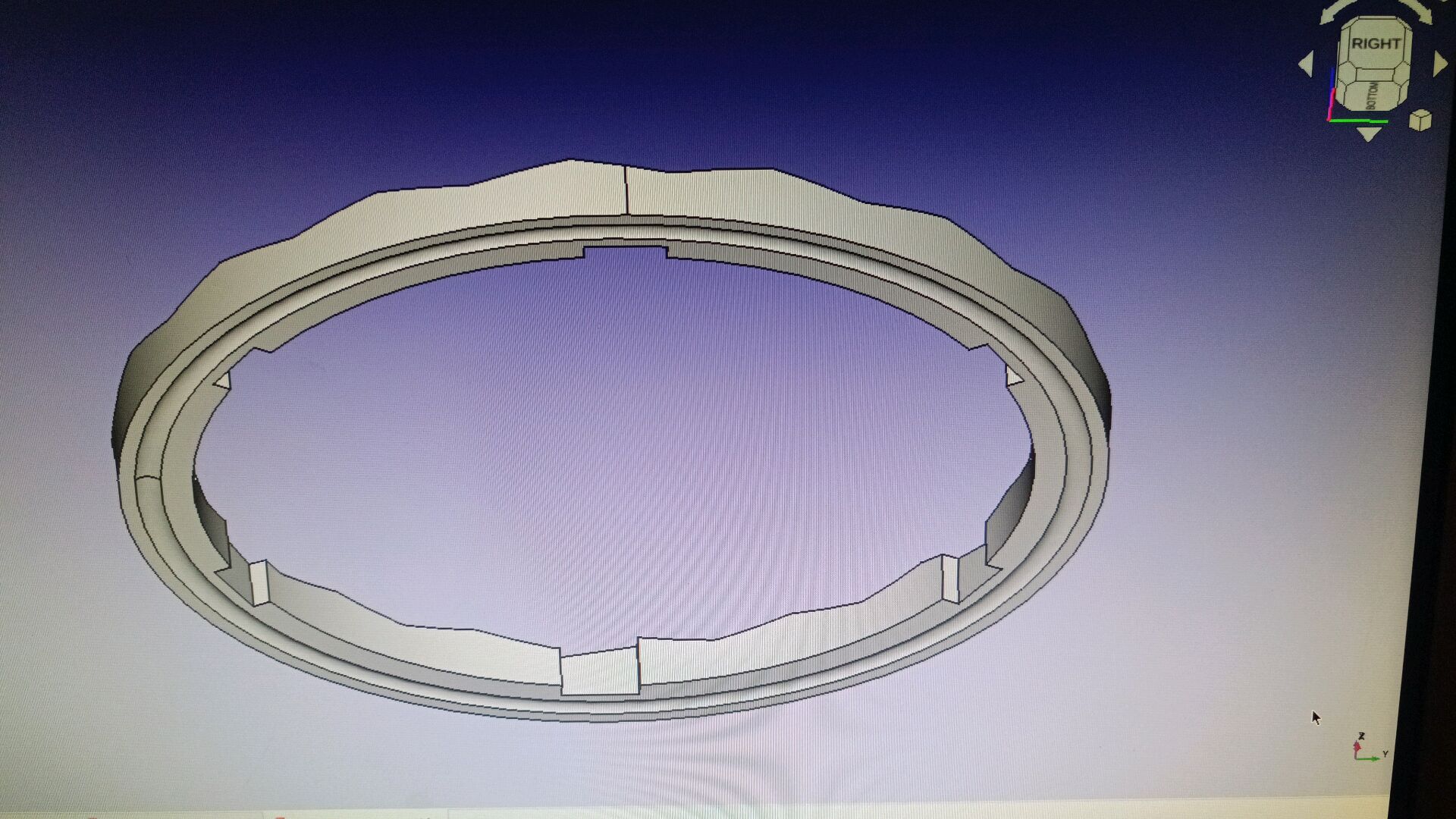
Drawing of the symmetrical replacement:
Go for it:
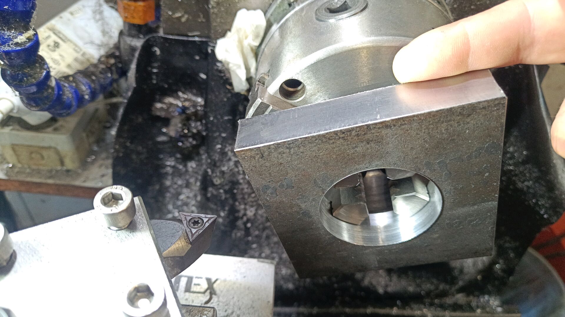
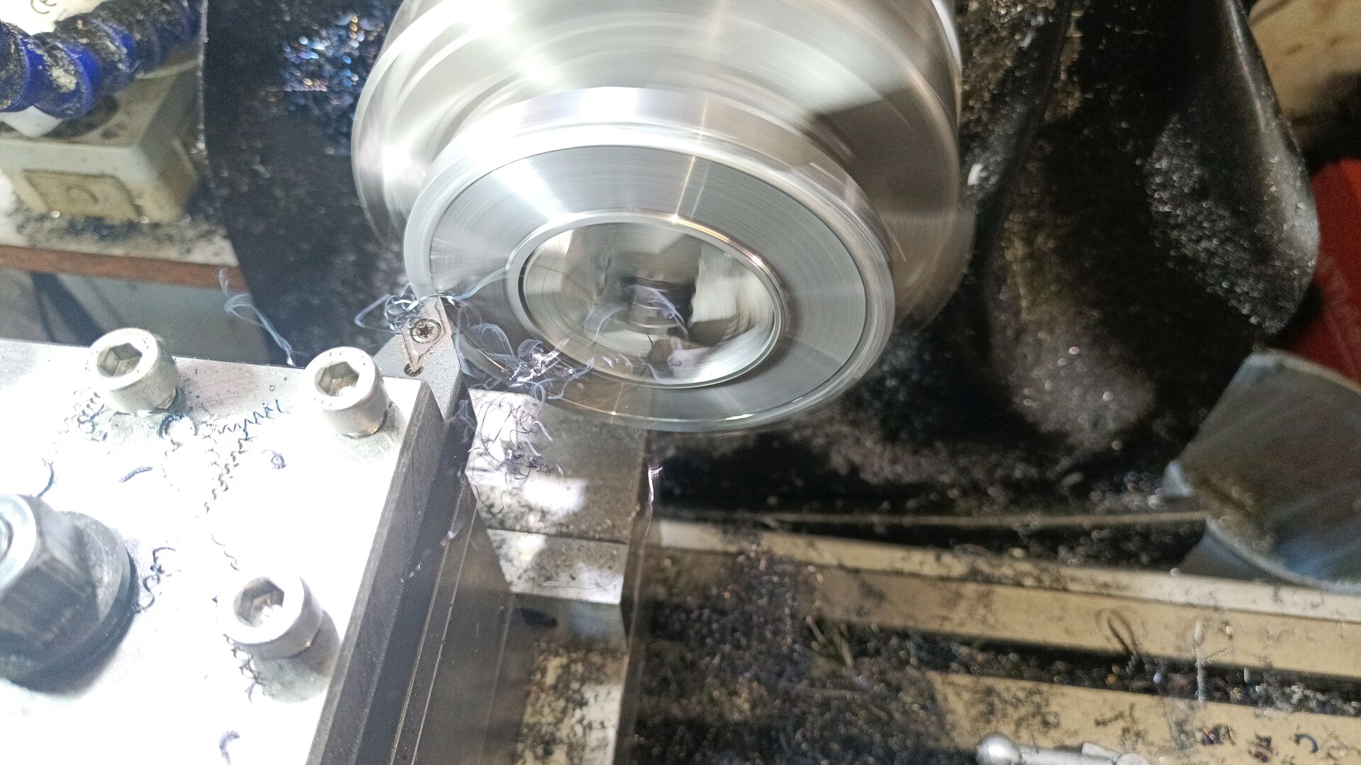
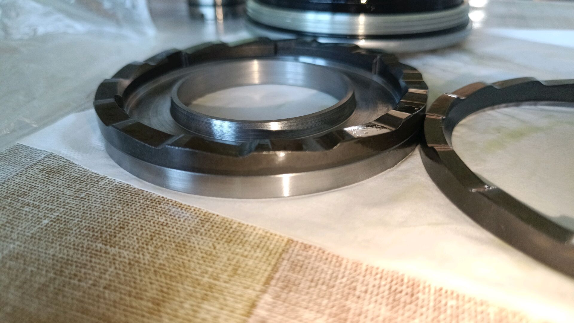
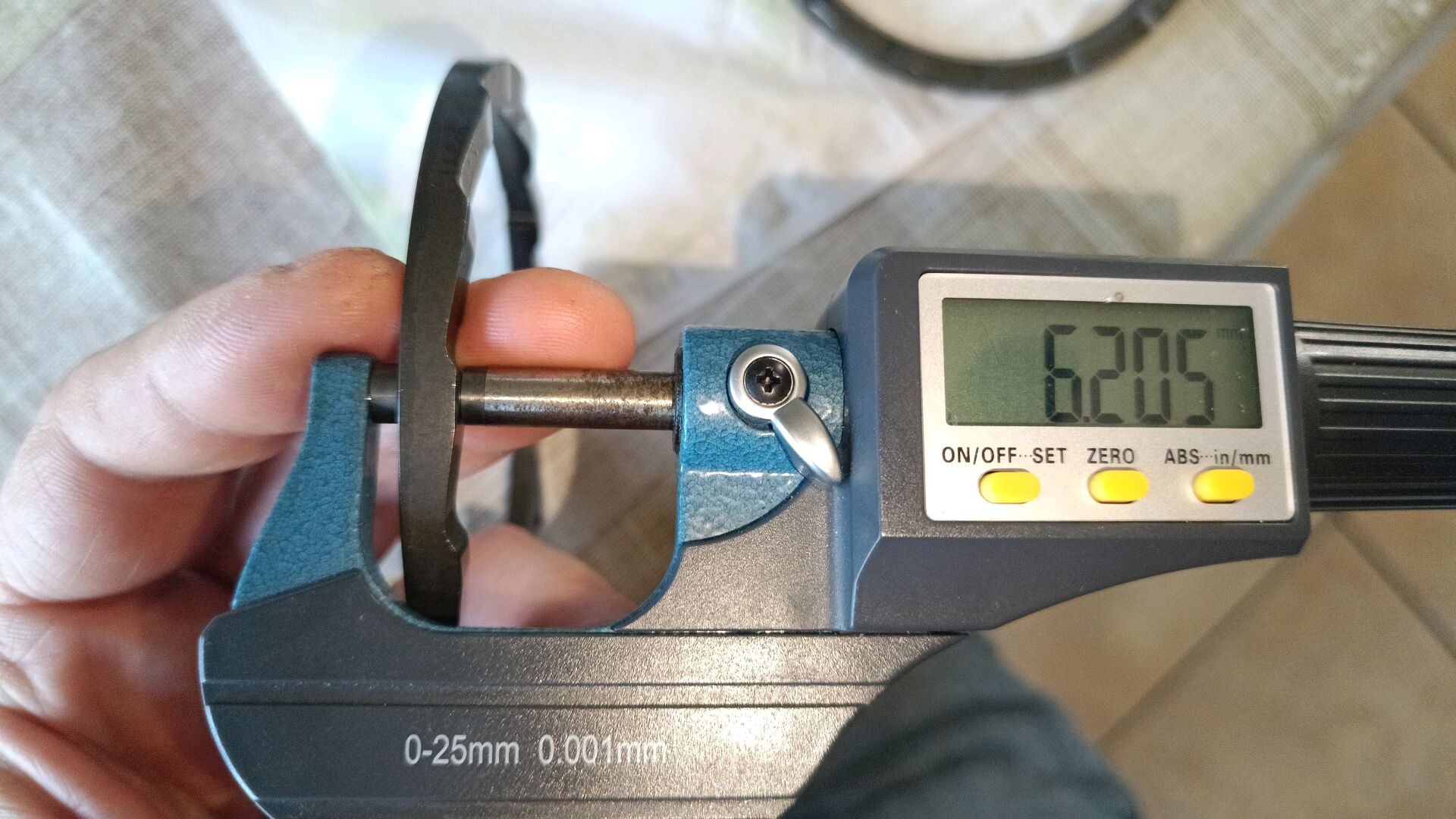
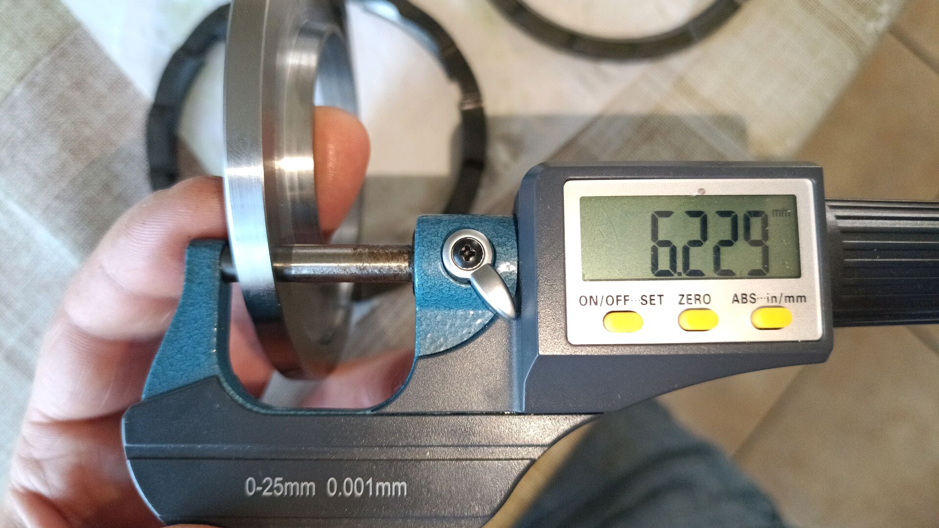
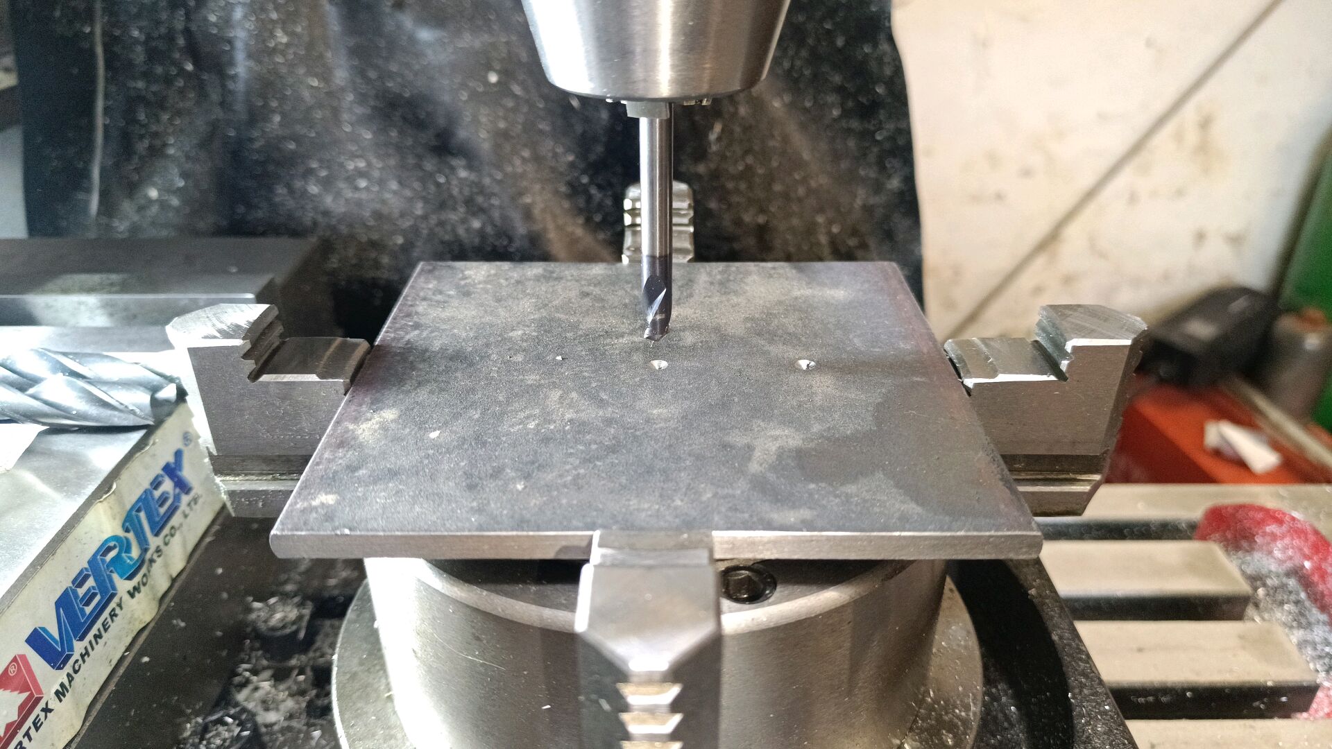
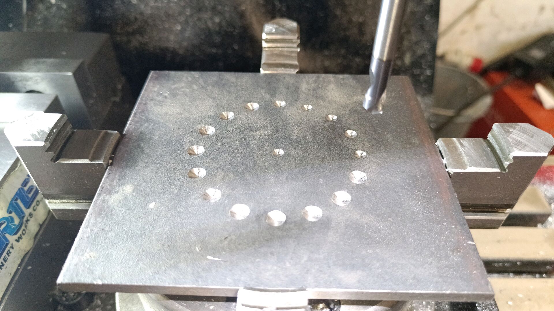
This is the raw ring. It is ready to be milled on the round table to get the symmetrical up and down ramps. Milling by hand. A single mistake and you start from the beginning.
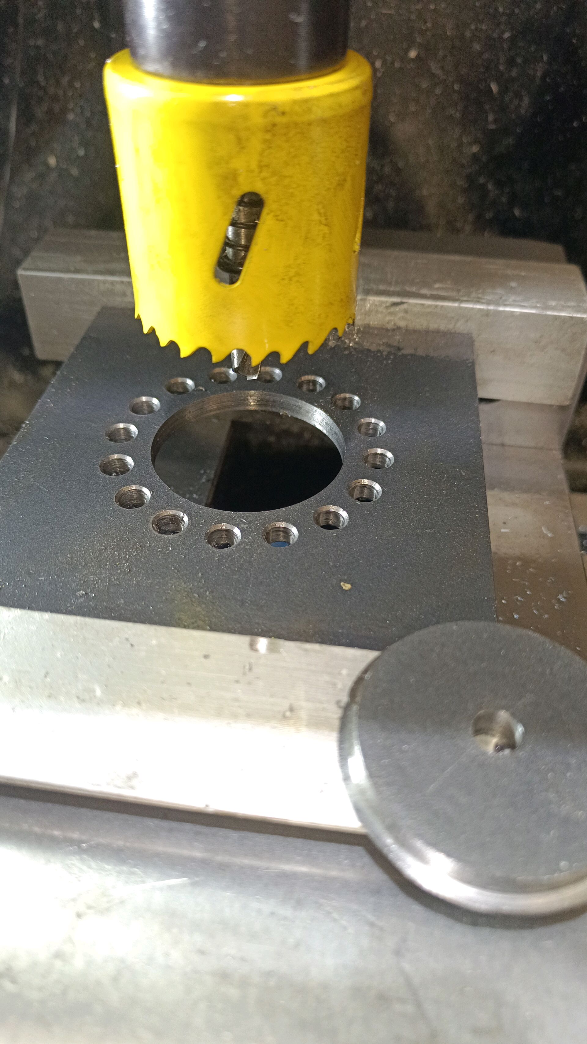
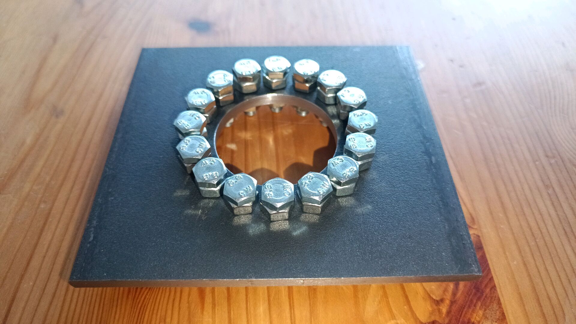
I noticed that the width of the 4 rings is not equal. So I created a fixture to plasma cut the next rings to become faster:
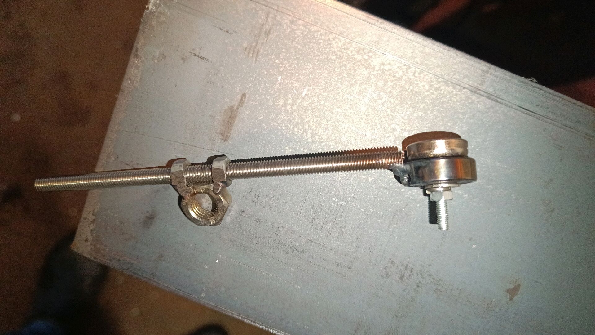
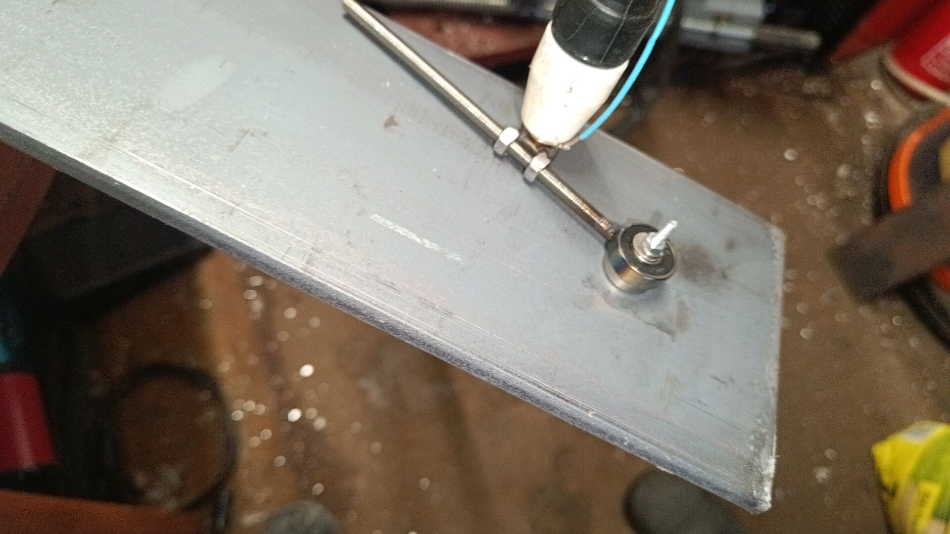
I take standard ST37 steel for the rings, which can’t be hardened. The balls directly run on the rings, so in reality the rings should be hardened. When hardening steel, it will distort and should be grounded to dimension, what I can’t do.
Till now I haven’t dismounted ring 3&4 yet- just no time to loosen a single screw. Many more projects, so I didn’t find time to go on. Don’t wait for me to continue.
3 Likes
Oh! Nice!
I’m looking at your stuff and trying to remember how the thing works. If memory serves me correctly, the weird thrust bearing presses onto the balls causing movement then when power is taken away, it stops pressing on the balls. Like a thrust version of a one way bearing. I have a few thoughts, #1 could you put some sort of spacer in it to keep it constantly pressed, #2 could you replace the rollers with square steel (I don’t think the rolling is necessary?), #3 could you machine a negative of the roller ring slightly oversized in thickness to press it, and #4 your symmetrical rings look like you’re trying to make a coaster brake+backwards, or are you just trying to stop the rollers from moving? (I’m looking at picture #11 top to bottom while thinking.
Also I love your solution for taking the hub apart, is it a right or left handed thread?
I don’t know if this is useful but just in case, a 15mm nut fits pretty snuggly into a 40mm bearing, but the 15mm nut from the hub itself is just slightly too big on the corners, you might be able to round them slightly


@Nathan_Moore , to answer your remarks:
That is correct.
Putting in a spacer will be feasible somehow, but I guess the friction will become enormous as well as the wear of the parts, which will loosen the parts rapidly. It should be spring loaded. The enormous friction remains.
Sure, sliding square steel has the same function as a roller, but it can not move to the opposite slope of my replacement ring when negative momentum is applied.
Yes, that should be fully functional. Like 2 replacement rings sliding on each other.
I intend that the rings compress at positive and negative momentum (the absolute value of the momentum is proportional to the compression force). The rollers aren’t fixed, they roll from one ramp to the other when the momentum changes it’s sign. That certainly leads to significant slack in the middle and isn’t ideal. A pressure pre-load would omit the slack. Adding a spring becomes complicated, although there is some sort of a spring near the freewheel clutch.
@Nathan_Moore , PM me in case you need my NUVINCI key pic#3.
My ideas are ways to keep the rings in constant contact with the balls but without the extra friction, a spacer might not work but the square steel would replace the rollers and be sized just enough to not slide. The negative of the roller ring probably isn’t the right word, I imagine taking the top and bottom slanted ring and placing their flat sides together and machining that (ramps on both sides of the ring, then put the normal rings together as if the machined piece was the roller ring) essentially performing a stronger version of the square steel idea. Are either of those possible?
The normal rings only function in one direction, they have to be the replacement rings anyways to have both directions. The precision of the parts in the hub is incredible, just to note all is ground to size and case hardened. Your ideas work, but actually the original bearings perform the same task. At that precision I have the cold welding effect in mind where the oil between the square sliders is pressed out over time and it cold welds because of precision ground surfaces at high pressure. The existing bearings avoid cold welding.
The NUVINCY thread is right handed:

The top rings and stuff are already taken out.
The Shimano megarange deraileurs will climb a 40 tooth cog but are much happier with a 39 tooth cog. I was the first to use a 46 tooth cog on the back of a bicycle and get it to work. This was with an even older Shimano deraileur with no model number on it. It had a 34 tooth next cog since the maximun jump with these deraileurs was 12 teeth. You might get more jump with a bigger pulley on the deraileur. 48_tooth_cog | 48 tooth cog made out of a chainring. The der… | Flickr